
Disposable bone cutting instrument

Inactive Publication Date: 2010-10-14
HOWMEDICA OSTEONICS CORP
View PDF7 Cites 46 Cited by
  • Summary
  • Abstract
  • Description
  • Claims
  • Application Information

AI Technical Summary

Benefits of technology

[0009]These and other aspects of the invention are provided by a helical reamer for reaming a bone cavity having a longitudinally extending support shaft having a first driven end and a second end having a tip for insertion into the bone cavity. A multiplicity of flat reamer plates are provided each having a plurality of cutting flutes formed on an external surface thereof and a central internal opening to receive the support shaft. The internal opening has a coupling element rotationally coupling each reamer plate to the support shaft. The coupling element allows each reamer plate to be slightly rotated with respect to the flutes of an adjacent reamer plate. At least some of the reamer plates have a different external cross-section. Preferably the reamer plates have external cross-sections which progressively increase on moving from the second end of the support shaft towards the first end of the support shaft. In one embodiment each plate internal opening includes an inwardly extending tab for engaging a groove on an outer surface of the support shaft, the groove extending between the first and second ends of the shaft. The groove may extend helically around an outer surface of the shaft or the groove may extend parallel to a rotational axis of the support shaft. Alternatively internal opening of each plate is part circular with a flat portion along one side of the opening and the support shaft has a corresponding flat portion along an outer surface thereof for mating with the flat portion on the plate. The flat portion of the shaft extends helically around the outer surface of the support shaft between the first and second ends of the shaft.

Problems solved by technology

Most importantly, the manufacturing costs associated with orthopedic reamers have traditionally been high.
These high costs have required such reamers to be utilized in multiple procedures.
This re-use requires the cleaning and sterilization of such a reamer before each use, which adds significant additional costs.
Improper cleaning and sterilization can lead to disease transmission.
Furthermore, multiple uses of a reamer create the greater probability of failure due to fatigue and / or poor cutting due to wear of the cutting surfaces of the reamer.

Method used


Image

  • Disposable bone cutting instrument
  • Disposable bone cutting instrument
  • Disposable bone cutting instrument

Examples


Embodiment Construction

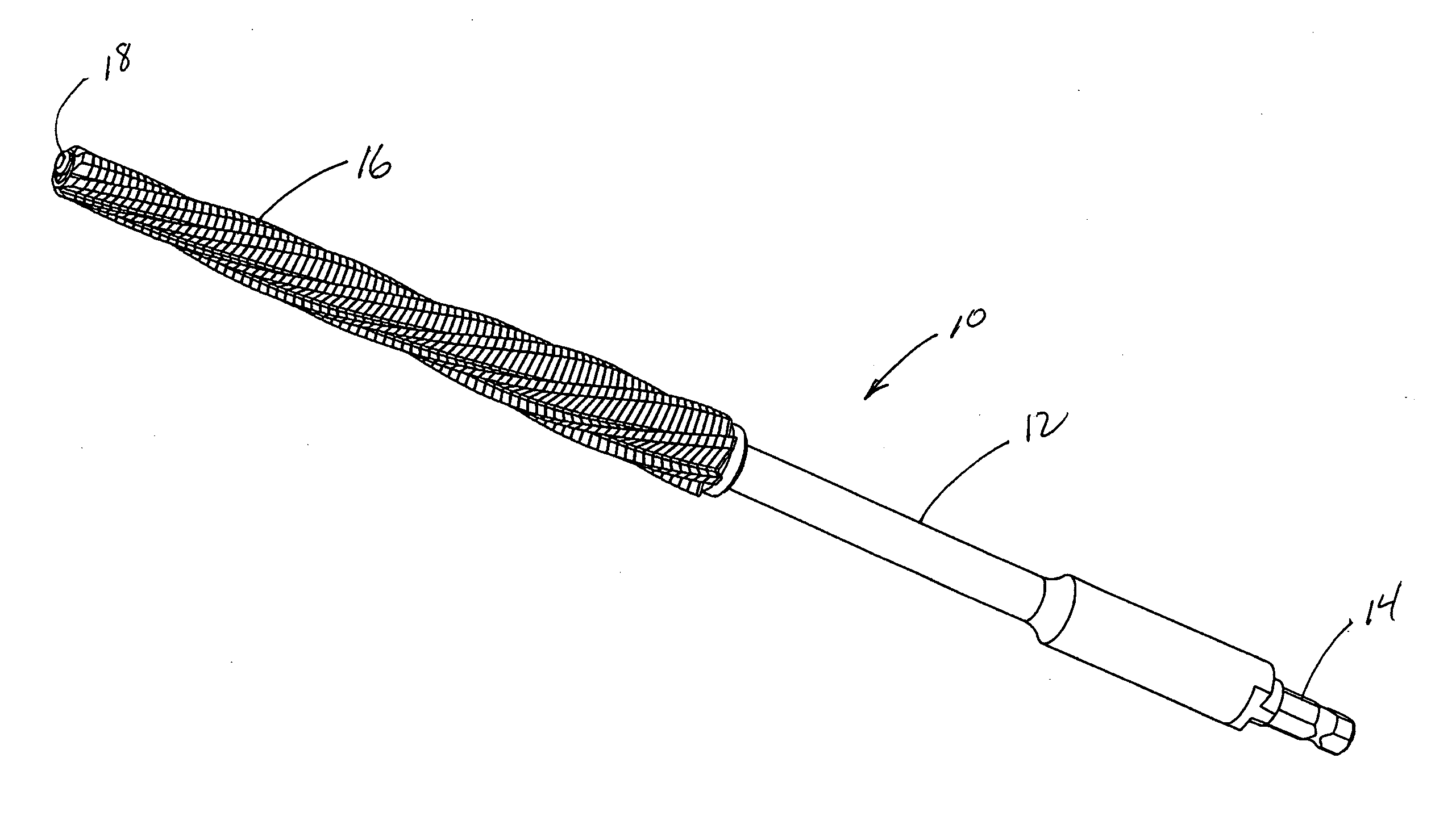
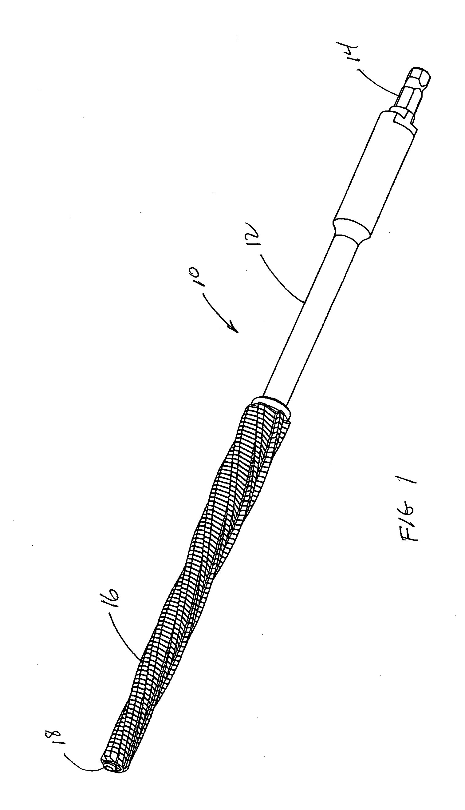
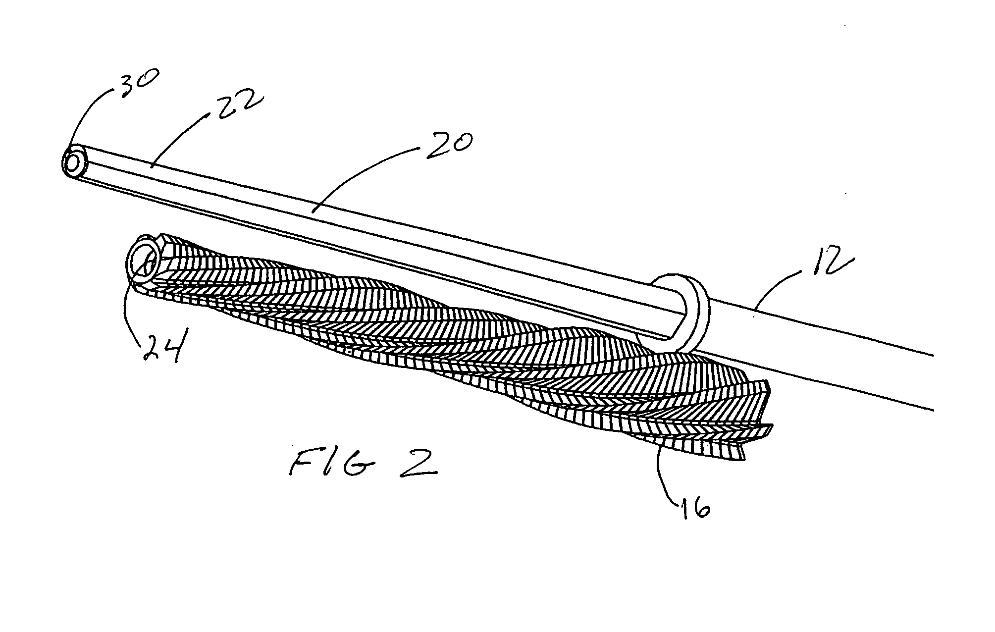
[0023]Referring to FIG. 1 there is shown an isometric view of a reamer generally denoted as 10 including a shaft 12 with a drive end 14 and a leading cutting end 16 including a leading tip 18. Drive shaft 12 may be either made of metal or plastic. Referring to FIG. 2 there is shown the reamer of FIG. 1 with the cutting portion 16 removed from a leading end 20 of drive shaft 12. In the preferred embodiment the leading shaft 20 of drive shaft 12 includes a flattened portion 22 shaped to engage a flattened portion 24 located within the hollow interior 26 of cutting portion 16. In the preferred embodiment the flattened portion 22 of shaft portion 20 is surrounded in part by a portion 28 rotatably coupled to portion 22 by a key 30.

[0024]As best shown in FIG. 3, cutting portion 16 is composed of a multiplicity of individual slices or plates 32. As can be seen in both FIGS. 2 and 3, plates 32 preferably are larger at an end of the cutter adjacent the drive end 14 of shaft 12 and gradually ...


PUM

PropertyMeasurementUnit
Angleaaaaaaaaaa
Lengthaaaaaaaaaa
Sizeaaaaaaaaaa

Abstract

A helical reamer for reaming a bone cavity has a longitudinally extending support shaft having a first driven end and a second end having a tip for insertion into the bone cavity. The research for a multiplicity of stamped flat reamer plates each having a plurality of cutting flutes formed on an external surface thereof and a central internal opening to receive the support shaft. The internal opening includes a coupling element in the form of a key and keyway rotationally coupling each reamer plate to the support shaft. The key and keyway allowing each reamer plate to be slightly rotated with respect to the flutes of an adjacent reamer plate. The coupling elements for rotationally coupling the plates to the drive shaft can be mating flattened areas on the internal surface of the stamping and the external surface of the drive shaft. A broach of stamped plates is also shown.

Description

BACKGROUND OF THE INVENTION[0001]The present invention relates to the field of instruments for the implantation of prostheses, and more specifically to reamers, for forming the inside cavity of a bone for receipt of a complimentary prosthesis. More particularly, to an orthopedic reamer that has been designed to permit the use of low-cost manufacturing methods while being durable and still maintaining its ability to create such canals.[0002]The replacement of joints, most frequently hips, in persons having damaged, diseased or malformed joints has become more and more frequent. Since hip replacement is the most common of such operations, the same will be described herein as exemplary of use of the present invention. Such instruments could be used in humeral cavity preparation as well.[0003]In the case of hip replacements, some operations involve the replacement of the ball or proximal end of the femur with a suitable prosthesis, while other such operations also include the installati...

Claims


Application Information

Patent Timeline
IPC IPC(8): A61B17/00B21K5/04
CPCA61B17/1668B23P2700/12B23P15/46A61B2017/00526A61B17/1659
Inventor TULKIS, PETER
Owner HOWMEDICA OSTEONICS CORP
Features
  • Generate Ideas
  • Intellectual Property
  • Life Sciences
  • Materials
  • Tech Scout
  • Unparalleled Data Quality
  • Higher Quality Content
  • 60% Fewer Hallucinations
Learn More