
Automated control method for a solar protection screen installation comprising retroreflecting-type slats

Inactive Publication Date: 2010-10-14
SOMFY ACTIVITES SA
View PDF10 Cites 1 Cited by
  • Summary
  • Abstract
  • Description
  • Claims
  • Application Information

AI Technical Summary

Benefits of technology

[0018]The aim of the invention is to provide a control method that avoids the previously stated drawbacks and improves on the control methods known from the prior art. In particular, the invention proposes a control method for a protection screen that makes it possible to obtain optimum visual comfort inside a space equipped with the screen.

Problems solved by technology

These blinds cannot be controlled automatically in the conventional way.

Method used


Image

  • Automated control method for a solar protection screen installation comprising retroreflecting-type slats
  • Automated control method for a solar protection screen installation comprising retroreflecting-type slats

Examples


Embodiment Construction

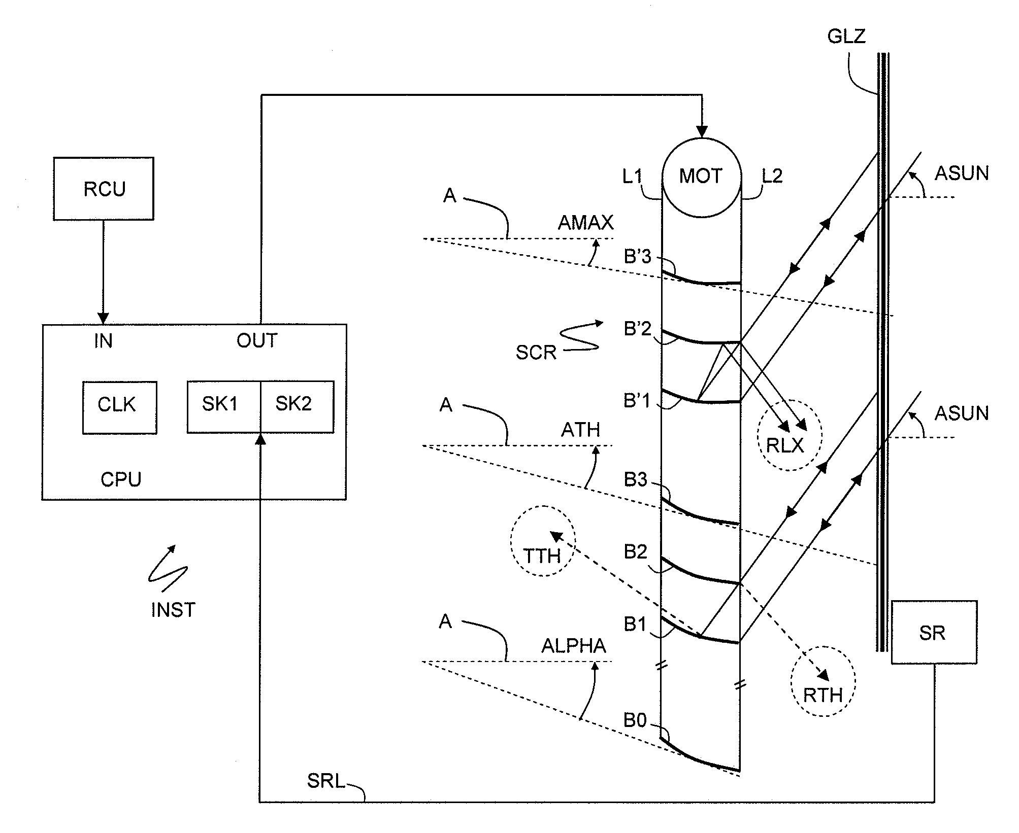
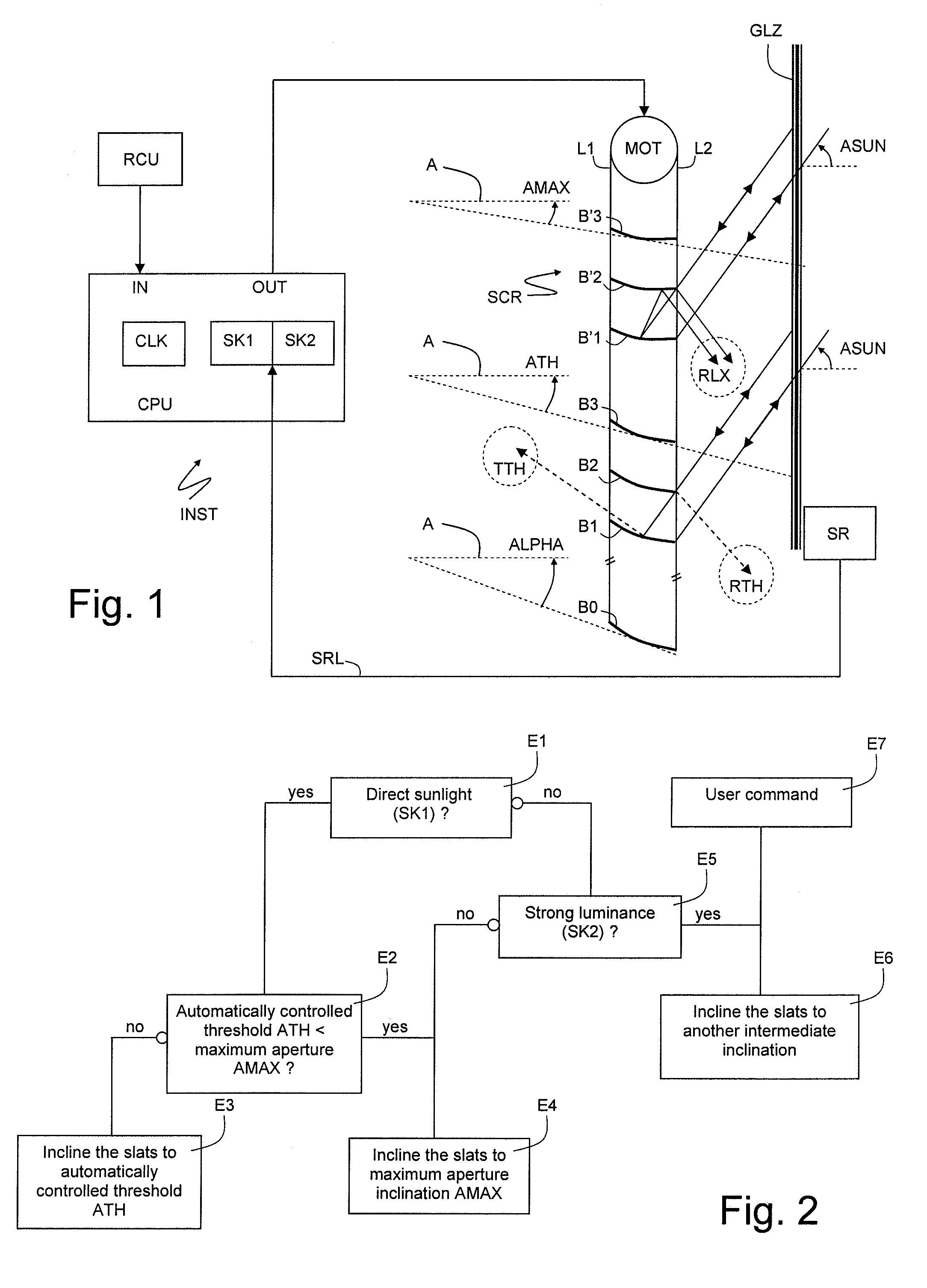
[0028]The installation INST comprises a solar protection screen SCR consisting of slats B1, B2, B3 (or B′1, B′2, B′3) guided in terms of orientation by ladders L1 and L2 connected to a motor MOT.

[0029]The screen SCR is positioned behind a frontage window GLZ, in a space situated inside a building. Alternatively, the screen is positioned in front of the window, outside the building.

[0030]The slats are of retroreflecting, or catadioptric, type. Ideally, any ray incident on the slat is reflected in the incident direction. The behavior of a slat will here be said to be retroreflecting if this property is borne out overall, that is to say if, for at least the majority of the incident rays and of the points of incidence, any reflected ray is emitted in a cone of weak aperture (for example 30°) that includes the incident direction. The behavior may be retroreflecting within only a certain range of relative inclinations of the incident rays relative to the slats. Outside of such a range of ...


PUM


Abstract

An automated control method for a solar protection screen (SCR) installation (INST) comprising retroreflecting-type slats (B1, B2, B3) which can be inclined between two extreme inclinations, wherein, in the presence of direct solar radiation, the slats are inclined at a first intermediate inclination, equal to the maximum aperture inclination (AMAX) of the screen relative to a preferred direction, as long as an inclination threshold automatically controlled in relation to the height of the sun (ATH) remains less than the maximum aperture inclination.

Description

BACKGROUND OF THE INVENTION[0001]The invention relates to the automated control of slatted blinds, in particular when the slats have a retroreflecting-type effect.[0002]Depending on the case, these slats are slightly dished upward or downward.DESCRIPTION OF THE PRIOR ART[0003]Such blinds are described in the patents U.S. Pat. No. 6,367,937, U.S. Pat. No. 6,845,805 and U.S. Pat. No. 6,240,999, and in the work entitled “Dynamic Daylighting Architecture” by Helmut Köstler-Birkhäuser—ISBN 3-7643-6730-X.[0004]Such blinds are designed for fixed positioning. The drive system is envisaged mainly for a deployment / retraction operation, for example to enable the windows to be cleaned.[0005]These blinds cannot be controlled automatically in the conventional way.[0006]It is known practice, in the presence of direct sunlight, to orient the median plane of the conventional blind slats in such a way that it is substantially perpendicular to the solar rays. In some cases, as in the patent U.S. Pat. ...

Claims


Application Information

Patent Timeline
IPC IPC(8): E06B9/32G05B11/01G05D3/10
CPCE06B9/32E06B2009/6827E06B9/386E06B2009/2417
Inventor GREHANT, BERNARDLAGARDE, ERIC
Owner SOMFY ACTIVITES SA
Learn More