Fitting for corrugated conduit

Active Publication Date: 2010-10-21
ROYAL GROUP
View PDF30 Cites 9 Cited by
  • Summary
  • Abstract
  • Description
  • Claims
  • Application Information

AI Technical Summary

Benefits of technology

[0006]It is an object of the present invention to improve a

Problems solved by technology

However, because of the configuration of both the fingers of the annular ring and the fitting body, the fingers are concealed to the user when the user begins to introduce the fingers of the annular ring into the fitting body, thereby preventing the user to accurately control the alignment of the fingers with the apertures of the fitting.

Method used


Image

  • Fitting for corrugated conduit
  • Fitting for corrugated conduit
  • Fitting for corrugated conduit

Examples


Embodiment Construction

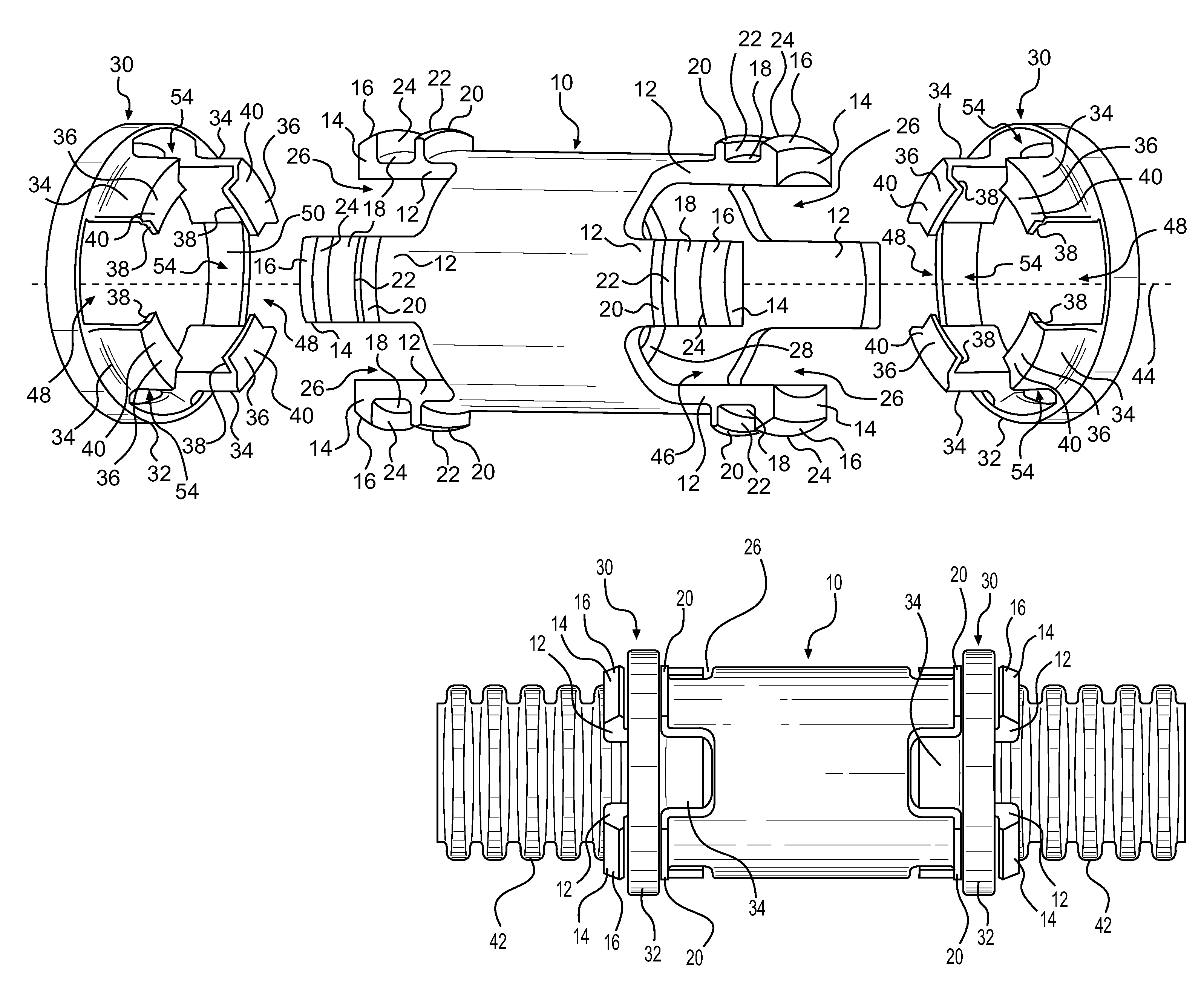
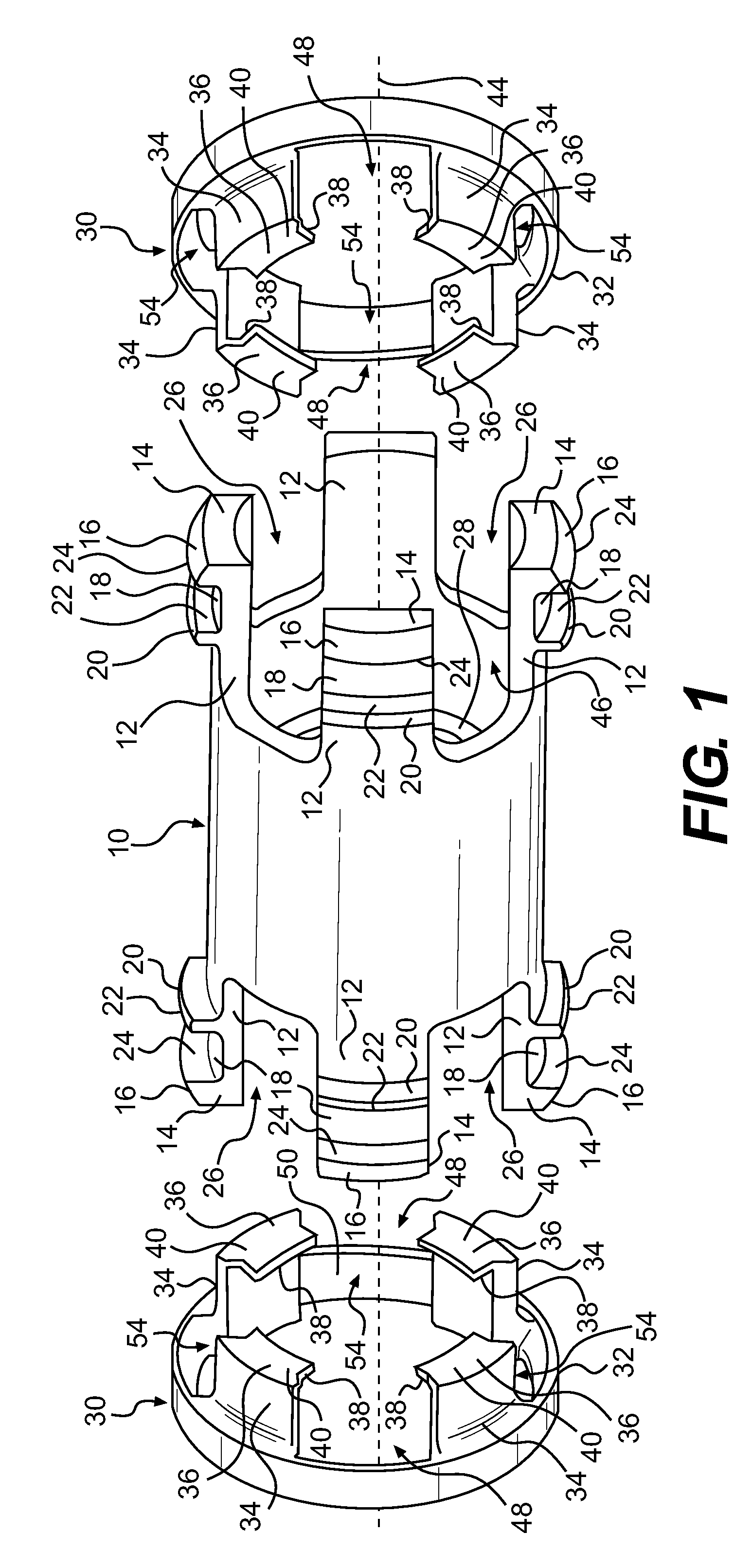
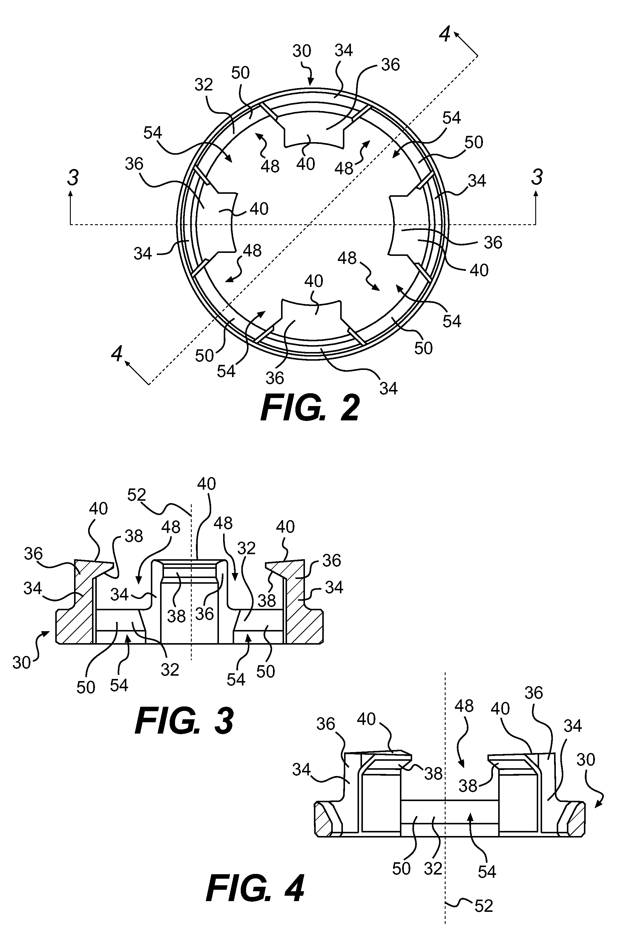
[0044]Referring to the drawings and initially to FIGS. 1-6, a fitting for joining a corrugated conduit to a structure associated with the fitting in accordance with the present invention will be described. The fitting comprises a generally cylindrical hollow fitting body 10 and retaining rings 30.

[0045]The fitting body 10 is made of injection-molded PVC and the retaining ring 30 is made of polycarbonate. A fitting body and a retaining ring made of injection-molded ABS plastic or of any other suitable plastic material such as polycarbonate, and polypropylene are also contemplated.

[0046]As shown on FIGS. 1, 5, and 6, the fitting body 10 defines an inner chamber 46 therein and comprises body resilient tabs 12 extending from each end of the fitting body 10 in an axial direction of the fitting body 10 (i.e. in a direction parallel to a central axis 44). The body resilient tabs 12 are arranged in diametrically opposed sets and define body gaps 26 therebetween. As best shown on FIG. 6, eac...


PUM


Abstract

A fitting for joining a corrugated conduit to a structure associated therewith is disclosed. The fitting comprises a hollow body having an inner chamber and at least two body resilient tabs extending from an end. The at least two body resilient tabs define at least two body gaps therebetween. Each of the at least two body resilient tabs defines an outwardly extending detent. The fitting also comprises a retaining ring including a flange and at least two ring resilient tabs extending from the flange and defining ring gaps therebetween. Each of the at least two ring resilient tabs defines an inwardly extending detent adapted to engage a corrugated conduit. Each of the at least two body resilient tabs is selectively inserted in a corresponding one of the at least two ring gaps, and the outwardly extending detents selectively engage an end of the flange of the retaining ring.

Description

FIELD OF THE INVENTION[0001]The present invention relates to a fitting for connecting a corrugated conduit to an associated structure.BACKGROUND OF THE INVENTION[0002]Corrugated and non-corrugated thermoplastic tubings are widely used as conduits for protecting wiring cables extending between various control boxes, switch boxes, and the like. Conventionally, to facilitate the installation and use of such tubing, push together or “snap together” type connectors have been used to allow tubing sections to be joined to each other or to system components quickly and without requiring special tools or adhesives.[0003]Different connector designs have been proposed for this purpose. These prior connector designs have varied from simple one piece type connectors using resilient tabs or fingers to more complex multi-component designs using multiple rings or other internal connector elements.[0004]U.S. Pat. No. 4,836,580 (the '580 patent) discloses one such design. The '580 patent discloses a ...

Claims


Application Information

Patent Timeline
IPC IPC(8): F16L25/00F16L37/098F16L55/00
CPCH02G3/0691H02G3/06Y10S285/903
Inventor SHEN, JAMESSMYTH, LORNEKEHREN, JOHN
Owner ROYAL GROUP
Why Eureka
Try Eureka