Valve cage for a pump

a valve cage and pump technology, applied in the direction of valve housings, functional valve types, transportation and packaging, etc., can solve the problems of promoting the wear and tear of pump components, and affecting the performance of the pump

Active Publication Date: 2010-10-28
FORD MICHAEL BRENT
View PDF6 Cites 28 Cited by
  • Summary
  • Abstract
  • Description
  • Claims
  • Application Information

AI Technical Summary

Benefits of technology

[0010]In accordance with another embodiment of the present invention, a valve cage is disclosed. The valve cage comprises, in combination: a housing having a north end and a south end, wherein a first interior portion of the housing proximate the north end includes a first threaded region and a second interior portion of the housing proximate the south end includes a second threaded region; and an insert adapted to be positioned in the housing, comprising, in combination: a base portion adapted to abut a seat, wherein the base portion includes an angled lip adapted to abut a third interior portion of the housing; a cradle portion adapted to releasably retain a ball, wherein the cradle portion is substantially cup-shaped; and a plurality of angled ribs, wherein each rib of the plurality of ribs extends upwardly from the base portion to the cradle portion, wherein the plurality of ribs define channels therebetween; wherein an exterior diameter of the cradle portion is less than an exterior diameter ...

Problems solved by technology

The ball and seat components used in both the traveling valve and the standing valve are exposed to excessive wear as a result of a number of factors.
This turbulent flow promotes wear of pump components.
In particular, in conventional pumping systems, the ball is allowed to move uncontrolled in the valve cage, eventually causing damage to both the ball and valve cage.
This causes great turbulence and slows the passage of fluid, reducing the volume of fluid that is allowed to pass.
As a result, over time, the action of the ball causes solids to accumulate.
Once the solids accumulate, they can prevent...

Method used


Image

  • Valve cage for a pump
  • Valve cage for a pump
  • Valve cage for a pump

Examples


Embodiment Construction

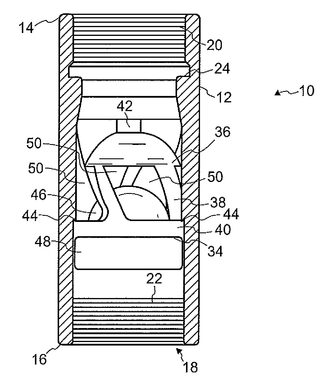
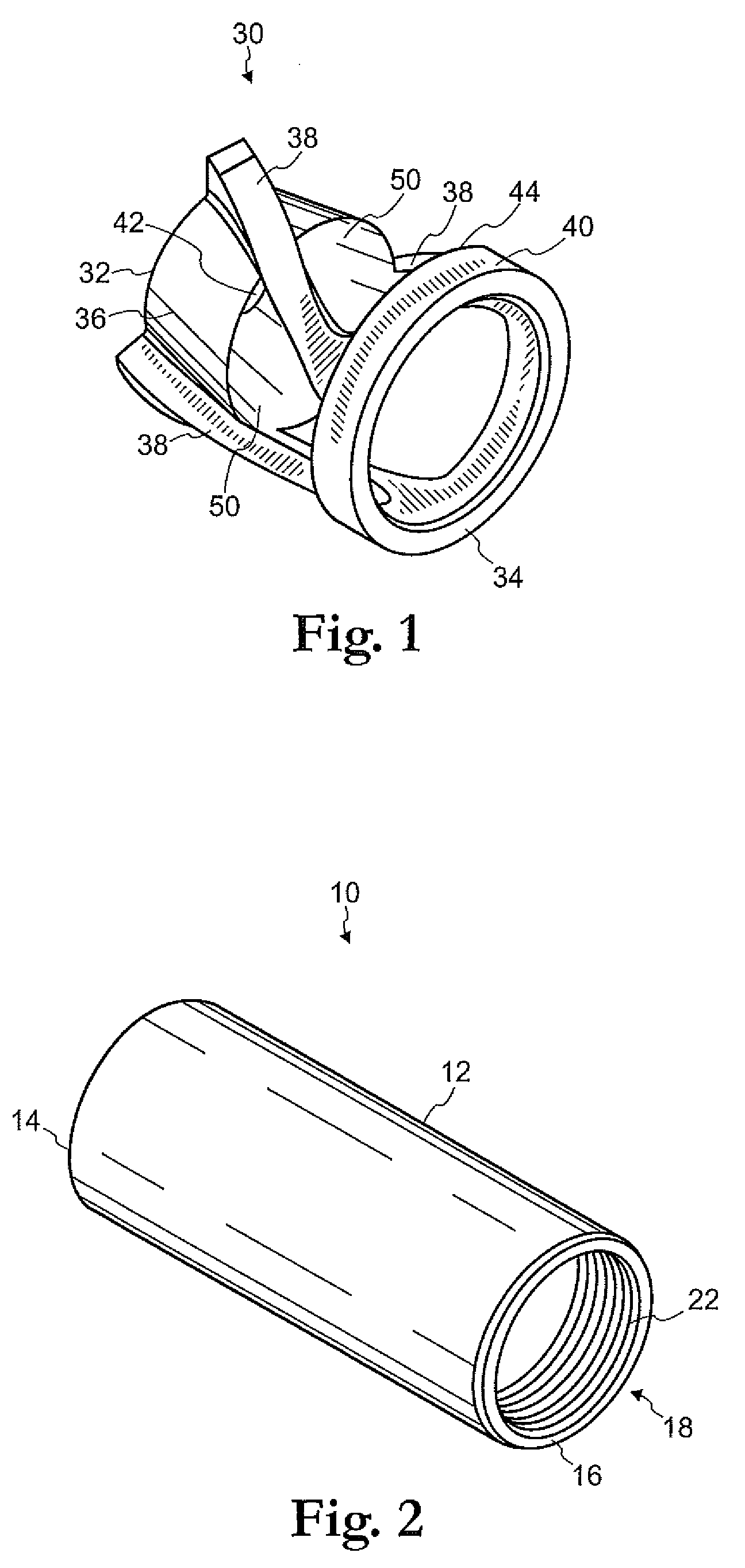
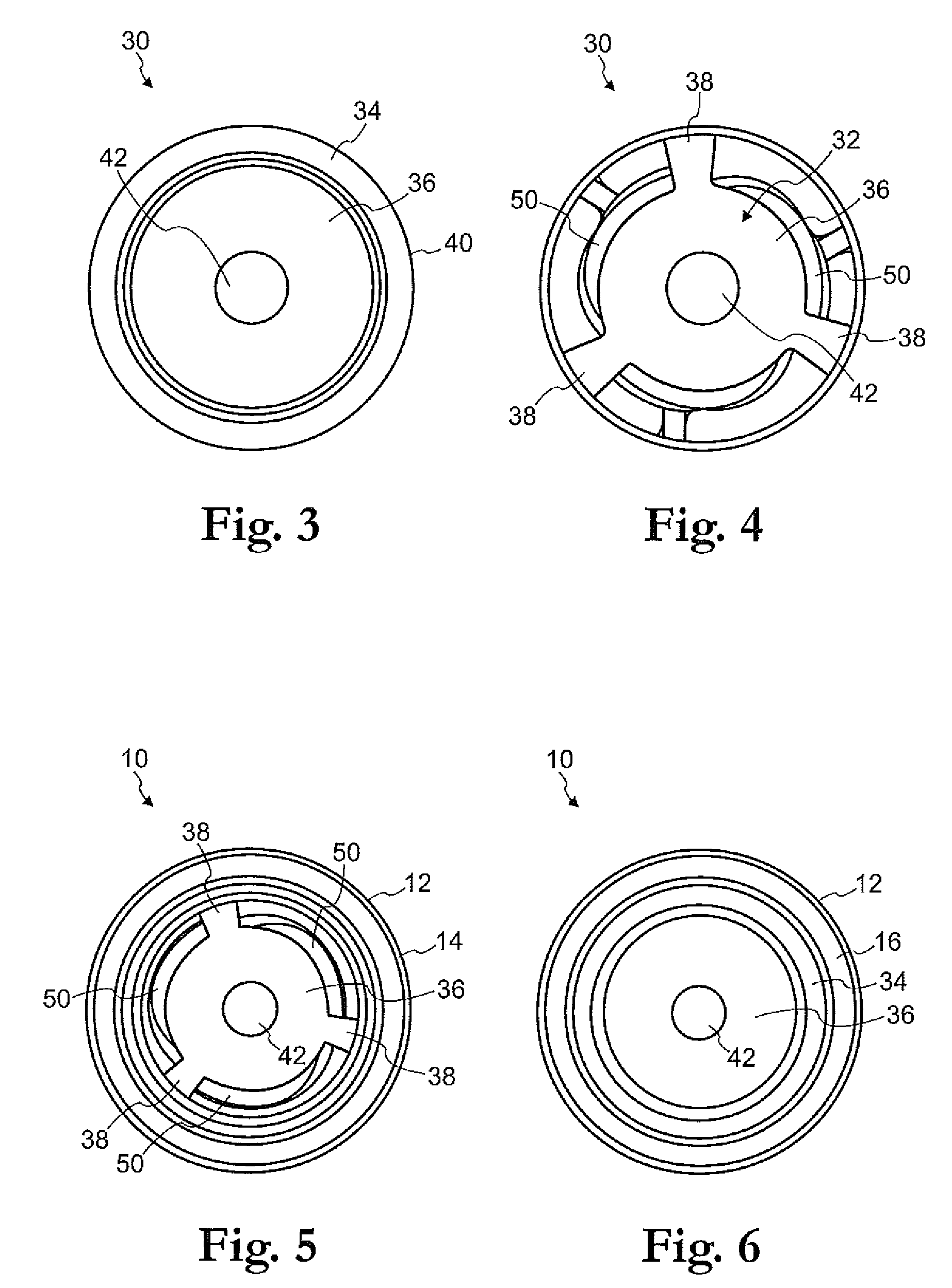
[0031]Referring first to FIGS. 2 and 8, a valve cage device 10 (“valve cage 10”) consistent with an embodiment of the present invention is shown. The valve cage 10 generally comprises the following basic components: a housing 12, and an insert 30 (as seen in FIG. 8, for example). The valve cage 10 is preferably a one-piece structure and may be composed of a hardened material, such as carbide, an alloy or some other suitable material capable of withstanding conditions present in typical oil well environments. In this embodiment, the valve cage 10 is configured as a traveling valve cage.

[0032]Turning first to the housing 12, the overall configuration of the housing 12 is substantially tubular. A longitudinal channel 18 runs through the housing 12, such that the housing 12 is adapted to receive insert 30 therein. The valve cage 10 includes a north end 14 and a south end 16. Referring to FIG. 7, an interior portion of the housing 12 proximate the north end 14 preferably includes a threa...


PUM


Abstract

A valve cage device is adapted for use with a subsurface pump or the like. The valve cage includes a housing and an insert. The insert includes a cradle, a plurality of angled ribs, and a base. In one embodiment, the insert may also include an extended nose region. A ball and seat may be positioned in the valve cage. During pumping operations, the cradle retains the ball when the ball is unseated, thereby allowing fluid to pass freely through channels in the insert and around the ball. This eliminates violent action of the ball, thereby obviating a need for a hard liner to be included in the valve cage. A port in the cradle allows fluid to pass therethrough when the ball has been released from the cradle. The angular configuration of the ribs provides for a more laminar flow of fluid compared with prior art valve cages, thereby providing improved passage of fluid through the valve cage. The base may include an angled hook or lip that creates a tight seal, thereby preventing fluid from washing by during pumping operations. During pumping operations, when the ball is released from the cradle, it is guided by the insert and falls straight downward onto the seat, allowing for faster seating of the ball, and in turn, reducing pump stroke loss and providing for more efficient pumping. The valve cage may be configured for a traveling valve or standing valve portion of a subsurface pump or the like.

Description

FIELD OF THE INVENTION[0001]The present invention relates generally to fluid pumping apparatuses and, more particularly, to a valve cage for use with a subsurface pump, that allows for improved flow of fluids during pumping operations.BACKGROUND OF THE INVENTION[0002]Oil well pumping systems are well known in the art. Such systems are used to mechanically remove oil or other fluid from beneath the earth's surface, particularly when the natural pressure in an oil well has diminished. Generally, an oil well pumping system begins with an above-ground pumping unit, which may commonly be referred to as a “pumpjack,”“nodding donkey,”“horsehead pump,”“beam pump,”“sucker rod pump,” and the like. The pumping unit creates a reciprocating (up and down) pumping action that moves the oil (or other substance being pumped) out of the ground and into a flow line, from which the oil is then taken to a storage tank or other such structure.[0003]Below the ground, a shaft is lined with piping known as ...

Claims


Application Information

Patent Timeline
IPC IPC(8): F16K15/04F16K15/02
CPCF16K27/0245F16K15/04Y10T137/7914Y10T137/791F16K2200/502
Inventor FORD, MICHAEL BRENT
Owner FORD MICHAEL BRENT
Why Eureka
Try Eureka