Display Device Having Two Operating Modes

a display device and operating mode technology, applied in the field of virtual images, can solve the problems of small size of portable devices and limits the size of the display module incorporated in said devices, and achieve the effect of increasing the weight and/or the size of the display device, and allowing the viewing aperture for virtual images to be substantially expanded

Inactive Publication Date: 2010-11-04
NOKIA CORP
View PDF13 Cites 294 Cited by
  • Summary
  • Abstract
  • Description
  • Claims
  • Application Information

AI Technical Summary

Benefits of technology

[0014]The virtual display mode allows viewing of images in privacy. On the other hand, the displayed real image may be viewed by two or more persons in e.g. meetings. Even when viewed by only one person, the real image displayed on an external screen allows ergonomic freedom of selecting a working position. The real image may be projected e.g. onto a white wall, onto the surface of a table, or onto a dedicated screen. The display device may be portable, lightweight and compact. A large detailed image may be examined at a glance in both operating modes.
[0015]Thanks to the use of the diffractive beam expander, the viewing aperture for a virtual image may be substantially enlarged without substantially increasing the weight and / or size of the display device.

Problems solved by technology

However, the small size of a portable device also sets a limitation to the size of a display module incorporated in said device.
A typical drawback of a conventional small display is that an observer can examine only a small portion of a large displayed image at a glance, while preserving adequate resolution.

Method used


Image

  • Display Device Having Two Operating Modes
  • Display Device Having Two Operating Modes
  • Display Device Having Two Operating Modes

Examples


Embodiment Construction

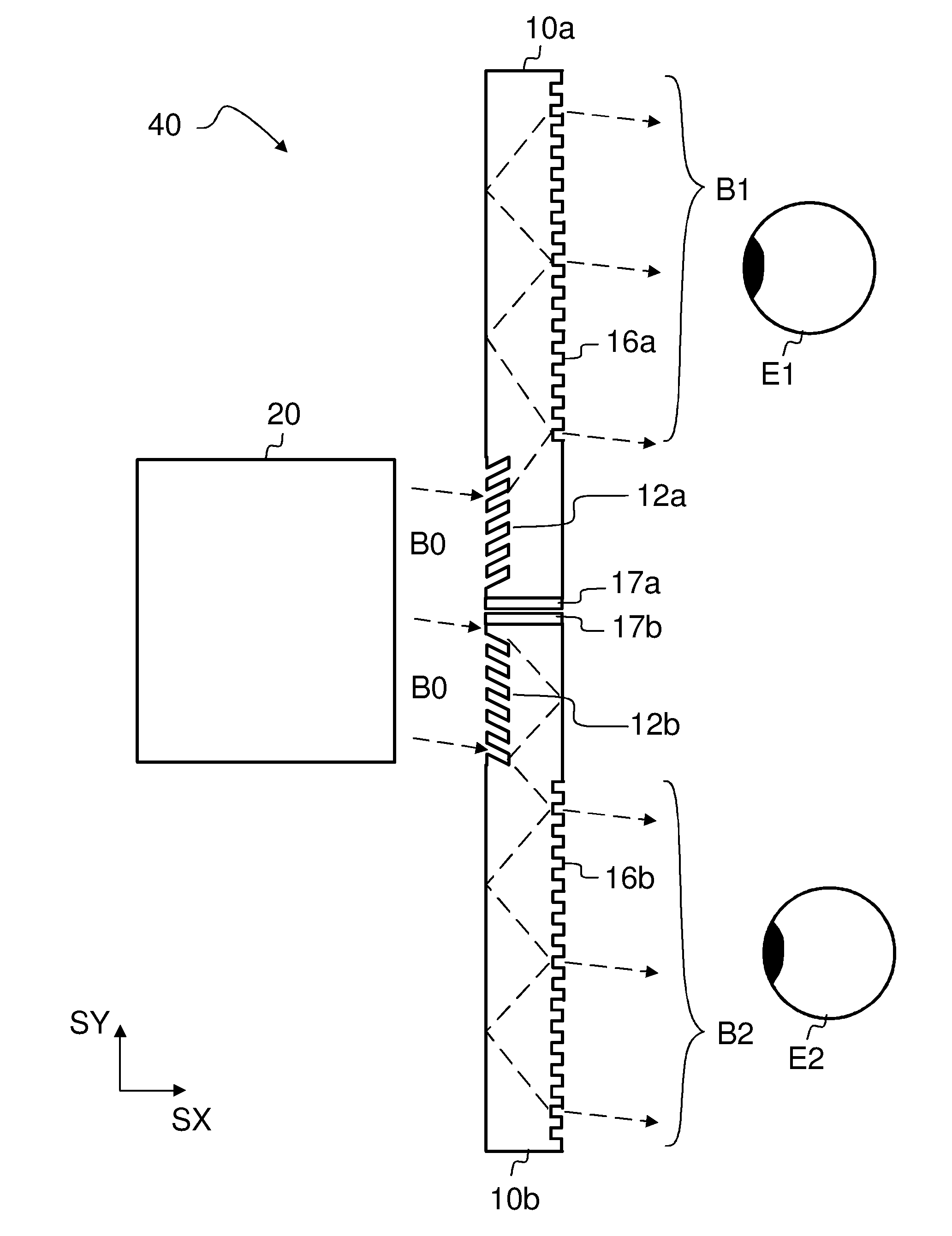
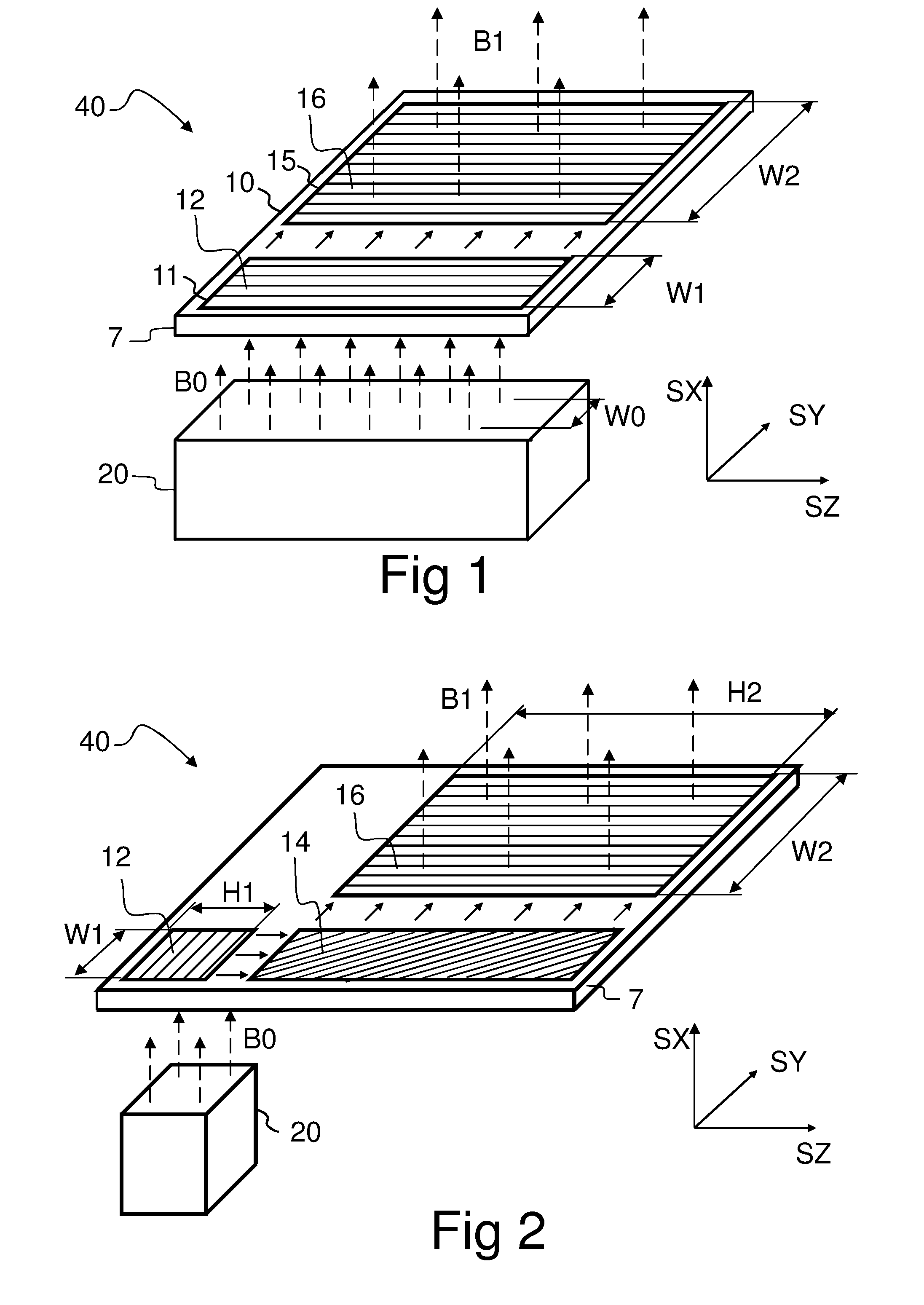
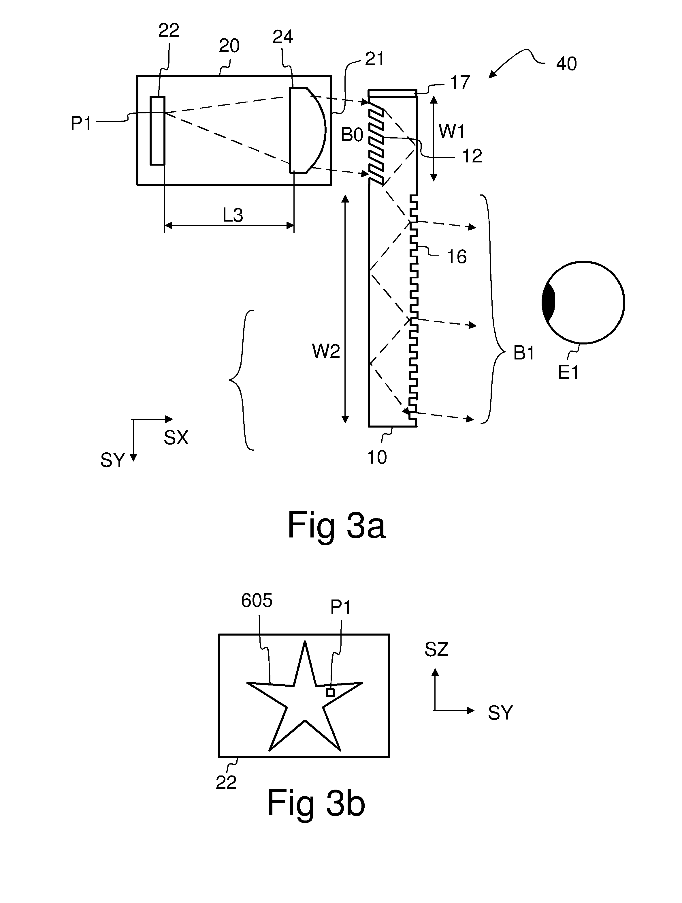
[0052]Referring to FIG. 1, a virtual display module 40 may comprise an optical engine 20 and a diffractive beam expander 10. The optical engine 20 comprises a micro-display 22 and imaging optics 24 (FIG. 3a). The virtual display module 40 converts a real primary image 605 (FIG. 3b) formed by the micro-display into a virtual image, which is observable through a viewing aperture 15 of the diffractive beam expander 10.

[0053]The diffractive beam expander 10 comprises an input grating 12 and an output grating 16 implemented on a common substantially transparent substrate 7. The upper and lower surfaces of the substrate 7 are substantially planar and substantially parallel. The substrate is waveguiding, which means that in-coupled light may propagate within said substrate 7 and such that said propagating light may be confined to said substrate 7 by total internal reflections. Light B0 impinging on the input grating 12 may be coupled into the substrate 7 such that it propagates within said...


PUM


Abstract

A display device (500) comprises a micro-display (22) and imaging optics (24) to transmit a light beam (BO), and a diffractive beam expander (10) having an output grating (16). The combination of said micro-display (22) and said imaging optics (24) is together adapted to form a virtual image (710) which is observable through the perimeter (15) of said output grating (16) when said diffractive beam expander (10) is positioned to at least partially intercept said light beam (BO). The combination of said micro-display (22) and said imaging optics (24) may also be adapted to project said light beam (BO) onto an external screen (600) in order to display a real image (610). The display device (500) may comprise a movable optical component (10, 380) to switch the device (500) from a virtual display mode to a projecting mode.

Description

FIELD OF THE INVENTION[0001]The present invention relates to displaying virtual images by using a micro-display, imaging optics, and a diffractive beam expander.BACKGROUND OF THE INVENTION[0002]Display modules are used in portable devices to display information in graphical form. Small size is an important aspect in portable devices. However, the small size of a portable device also sets a limitation to the size of a display module incorporated in said device. A typical drawback of a conventional small display is that an observer can examine only a small portion of a large displayed image at a glance, while preserving adequate resolution.[0003]An approach to display a large image by using a small display module is to use a near-eye display. A near-eye display based on a diffractive beam expander is disclosed e.g. in a patent application EP0535402SUMMARY OF THE INVENTION[0004]The object of the present invention is to provide a display device.[0005]According to a first aspect of the i...

Claims


Application Information

Patent Timeline
Patent Type & Authority Applications(United States)
IPC IPC(8): G02B27/02G02B27/44G02B27/22G03B21/00
CPCG02B5/18G02B6/0036G02B6/0038G02B6/0061G02B6/0068G02B6/0076G02B27/4277G02B2027/0123G02B2027/015G03B21/62G02B27/0081G02B27/4205G02B27/0172
Inventor POCKETT, LACHLANLEVOLA, TAPANIPARVIAINEN, JUKKASALMIMAA, MARJAVIINIKANOJA, JARKKOVIRTA, MARKUS
Owner NOKIA CORP
Why Eureka
Try Eureka