Coating structure and method for forming the same

a coating structure and coating technology, applied in the direction of superimposed coating process, liquid/solution decomposition chemical coating, instruments, etc., can solve the problems of insufficient water-shedding property, uneven fluorine-based film thickness, and inability to provide sufficient water-shedding properties

Inactive Publication Date: 2010-11-04
DENSO CORP
View PDF44 Cites 1 Cited by
  • Summary
  • Abstract
  • Description
  • Claims
  • Application Information

AI Technical Summary

Benefits of technology

[0013]The fluorine-based film is not formed directly on the metal member, but formed on the surface-smoothing layer which is formed on the metal member. Therefore, the coating structure can have the sufficient water-shedding property which is not reduced by heating. Further, the coating structure may be used for a metal member having the large surface roughness.
[0015]In the method, the fluorine-based film is not formed directly on the metal member, but formed on the surface-smoothing layer which is formed on the metal member. Therefore, the coating structure formed by the method can have the sufficient water-shedding property which is not reduced by heating, regardless of a surface roughness of the metal member.

Problems solved by technology

However, a thickness of the fluorine-based film is typically very thin, e.g., a few dozens nm.
Therefore, when the fluorine-based film is directly formed on the metal member having a large surface roughness, the fluorine-based film becomes uneven with a sink, and cannot provide a sufficient water-shedding property.
Therefore, the fuel injection nozzle has a problem that a large amount of foreign material, which is considered as a product generated from fuel, adheres to a needle of the fuel injection nozzle.
When the large amount of foreign material adheres to the needle, the foreign material may pile-up into a mass, and the mass may drop off between the nozzle body and the needle.
In this case, the needle may be difficult to slide, and furthermore, the needle may adhere to the nozzle body and an engine may fail to start.

Method used


Image

  • Coating structure and method for forming the same
  • Coating structure and method for forming the same
  • Coating structure and method for forming the same

Examples


first embodiment

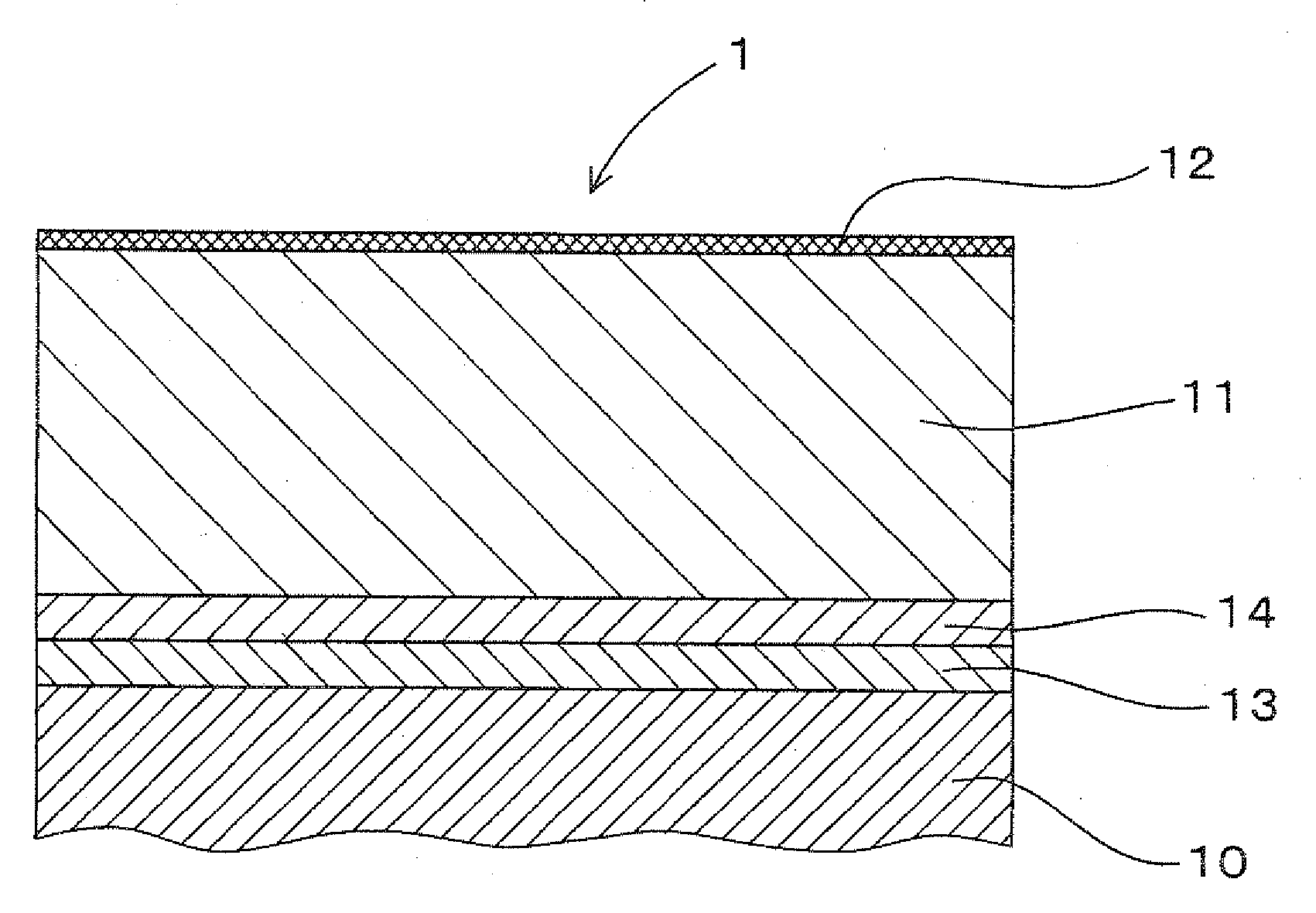
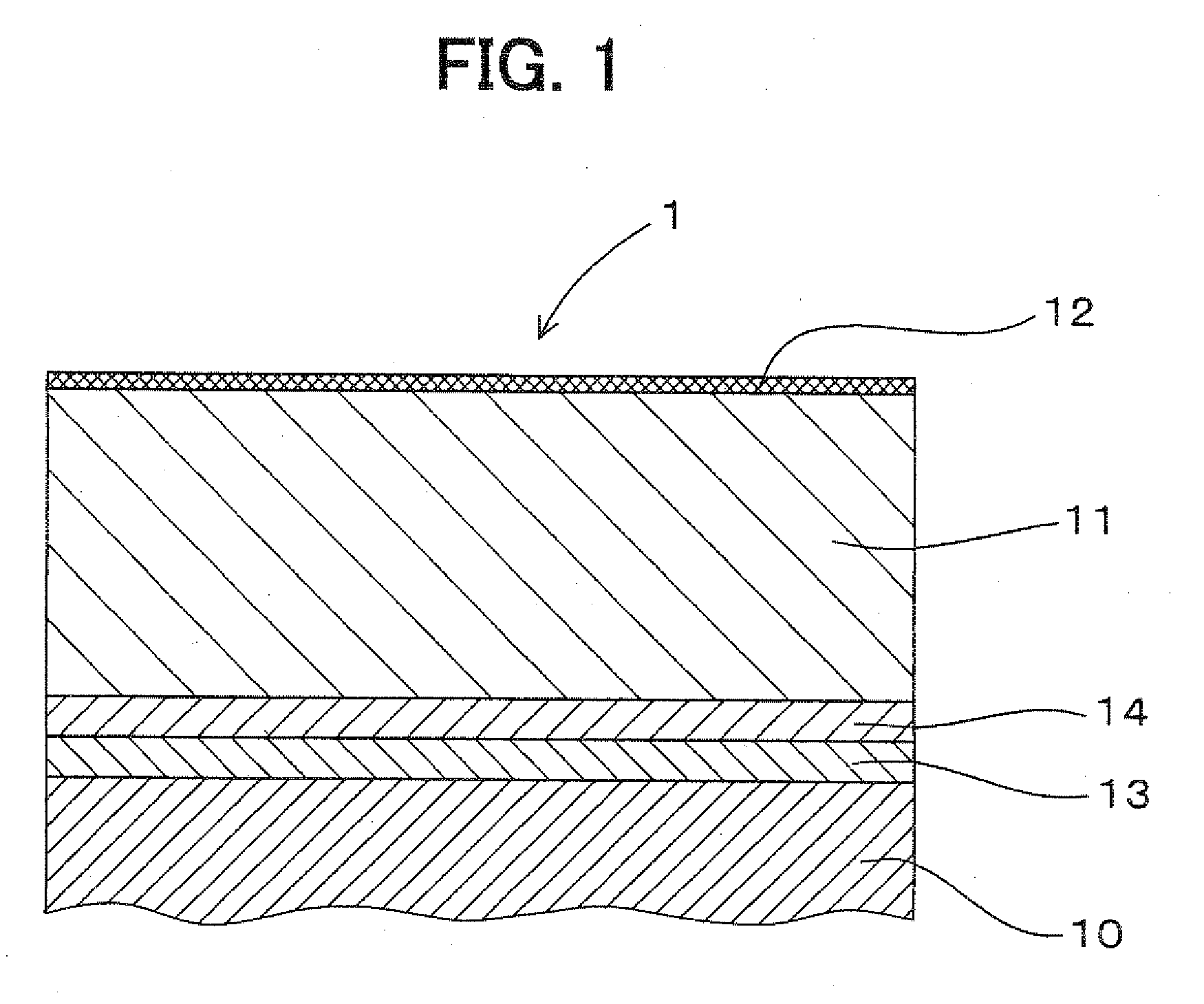
[0028]As shown in FIG. 1, a coating structure 1 according to a first embodiment of the invention includes a surface-smoothing layer 11 and a fluorine-based film 12. The surface-smoothing layer 11 for smoothing a surface of a metal member 10 is formed on the metal member 10, and the fluorine-based film 12 is formed on the surface-smoothing layer 11. As the surface-smoothing layer 11, a NiP / PTFE composite film (hereafter, composite film), in which PTFE (polytetrafluoroethylene) particles are dispersed in a NiP, is used. More details will be described below.

[0029]The coating structure 1 can be used for the metal member 10 made of a various metal-based material. An example material for the metal member 10 is a Fe-based material. When the coating structure 1 is formed on the Fe-based member 10, the coating structure 1 can provide a waterproof property (e.g., water-shedding property) effectively. In the first embodiment, an austenitic stainless steel (SUS304) consisting mainly of Fe is us...

second embodiment

[0060]In a coating structure E according to a second embodiment of the invention, the NiP / PTFE composite film 11 is formed directly on the metal member 10, and the fluorine-based film 12 is formed on the composite film 11.

[0061]The Ni strike film 13 and NiP film 14 described in the first embodiment are not formed in the second embodiment. In a coating structure C1 according to a first comparative example, only the fluorine-based film 12 is formed directly on the metal member 10. In a coating structure C2 according to a second comparative example, only the NiP / PTFE composite film 11 is formed directly on the metal member 10.

[0062]In each of the coating structures E, C1 and C2, the austenitic stainless steel (SUS304) is used as the material of the metal member 10 similarly to the first embodiment, and the surface roughness Rz(10) of the metal member 10 is 2 μm. Thicknesses and forming methods of the composite film 11 and the fluorine-based film 12 are similar to those of the first emb...

third embodiment

[0066]In a third embodiment, a coating structure 1 similar to that of the first embodiment is used for a fuel injection nozzle 7. As shown in FIG. 5, the fuel injection nozzle 7 can be used for a common-rail injection system of a diesel engine for injecting a high-pressure fuel into cylinders of the diesel engine. The injection nozzle 7 includes a nozzle body 71 and a needle 72. The injection nozzle 7 is set in a nozzle holder (not shown), and is attached to the diesel engine.

[0067]The nozzle body 71 includes a guide hole 710 in which the needle 72 is inserted, a sliding hole part 711 adjacent to an opening end part 719 of the guide hole 710, a fuel storing part 712 provided in the guide hole 710, a fuel introducing passage 713 connected to the fuel storing part 712, a cone-shaped valve seat 715 located at a leading end part of the guide hole 710, and a plurality of injection holes 714 provided to penetrate through the valve seat 715.

[0068]The guide hole 710 is provided in the nozzl...


PUM

PropertyMeasurementUnit
thicknessaaaaaaaaaa
surface roughnessaaaaaaaaaa

Abstract

A coating structure for a metal member includes a surface-smoothing layer formed on the metal member for smoothing a surface of the metal member, and a fluorine-based film formed on the surface-smoothing layer. The fluorine-based film can be formed by applying a fluorine-containing solution on the surface-smoothing layer, and by drying the fluorine-containing solution. The coating structure can be suitably used for a fuel injection nozzle.

Description

CROSS REFERENCE TO RELATED APPLICATIONS[0001]This application is a Division of application Ser. No. 11 / 798,240, filed May 11, 2007, which claims priority from and is based on Japanese Patent Applications No. 2006-133845 filed on May 12, 2006, and No. 2007-050745 filed on Feb. 28, 2007, the contents of each of which are incorporated herein by reference in its entirety.BACKGROUND OF THE INVENTION[0002]1. Field of the Invention[0003]The present invention relates to a coating structure including a fluorine-based film on a metal member, and a method for forming the same.[0004]2. Description of the Related Art[0005]Conventionally, in order to provide a water-shedding property to a member such as a metal member, a coating structure including a fluorine-based film is used, for example. The coating structure can be used for a member which is heated and is required to have an antifouling property, e.g., a vehicle component such as a fuel injection nozzle as disclosed in JP-A-8-144893, and a h...

Claims


Application Information

Patent Timeline
Patent Type & Authority Applications(United States)
IPC IPC(8): B32B15/08B32B27/06B32B5/16B32B5/00
CPCC23C18/1628Y10T428/12583C23C18/1651C23C18/1662C23C18/32C23C28/00F02M61/10F02M61/168F02M2200/02F02M2200/9038F02M2200/9046C23C28/321C23C28/322C23C28/34C23C28/343Y10T428/265Y10T428/24405Y10T428/12569Y10T428/30Y10T428/254C23C18/165Y10T428/3154Y10T428/31544
Inventor ASANO, YASUSHIYANAGAWA, KEITASUGAWARA, HIROYOSHI
Owner DENSO CORP
Why Eureka
Try Eureka