Gas-insulated electrical installation provided with a device for dissipating energy produced by an electric arc

a technology of electric arc and gas insulation, which is applied in the direction of overvoltage protection resistors, substation/switching arrangement casings, emergency protective arrangements for limiting excess voltage/current, etc., can solve the problems of short circuit giving rise to electric arc of very high energy, electric arc from destroying the installation and its environment, and too violent escape of hot or inflamed gases outside the enclosure. , to achieve the effect of great efficiency

Active Publication Date: 2008-04-01
SCHNEIDER ELECTRIC IND SAS
View PDF5 Cites 6 Cited by
  • Summary
  • Abstract
  • Description
  • Claims
  • Application Information

AI Technical Summary

Benefits of technology

[0006]The object of the invention is therefore to overcome the drawbacks of the state of the art so as propose an electrical installation protected against the effects of the internal arc by a device that is inexpensive, not cumbersome, relatively light and of very great efficiency, both to absorb the shock wave emitted by the internal arc and to prevent propagation of hot or even inflamed gases, or post-combustion or spontaneous flaming phenomena of gases at a distance from the installation.
[0011]The presence of fine non-combustible airborne particles in the gas modifies both the stoechiometry of the mixture, its heat capacity and its kinetics. Globally it prevents self-combustion of the gas downstream from the layer.
[0014]Porous materials offer the advantage of a very low apparent density combined with a high heat capacity. Furthermore, these materials have a large surface roughness which enhances dissipation of energy by friction when the grains are agitated when the shock wave passes. Materials will preferably be chosen which combine porosity and friability. Among the materials giving interesting results, the following are noteworthy: pumice stone, pozzolana and Siporex®.
[0015]The layer of granular material preferably contains non-combustible solid dust, in disseminated manner in the solid granular material, to form said cloud. This arrangement avoids the risk of agglomeration of the dusts which could take place after a few years, for example in the presence of humidity or vibrations. Such an agglomeration would in fact be very harmful: the cloud of dusts would no longer be able to form and the agglomerated dust could even form a plug hindering the progression of the gases causing explosion of the installation. Naturally the presence of dust disseminated in the material is not incompatible with the choice of a friable material, quite on the contrary.
[0017]Advantageously, the layer is arranged downstream from the sealing means. The gas removal path broadens out from the sealing means to the layer, forming a gas expansion volume. The gas removal path presents an opening section, at the level of the sealing means, the layer presenting a free external surface situated facing the sealing means having an area larger than three times the area of the opening section. Under the geometric conditions thus defined, the gas shoots out at the level of the sealing means in the form of a dart. The efficiency of the layer of material enables the latter to be arranged in the dart. The gas expansion zone situated between the sealing means and the layer of granular material is thus greatly reduced, which enables the surface of the walls confining the gas removal path to be reduced, whence less stress being exerted on these walls by the pressure wave reaching the layer, and limitation of the deformations of the installation.
[0019]This arrangement enables, in the event of an internal arc generating a pressure or shock wave, a large deformation of the material in the zone directly facing the orifice which absorbs the shock wave energy and prevents propagation thereof beyond the layer of granular material. The use of a very rough and / or friable granular material enables the layer of material to be located considerably closer to the communication orifice, which contributes to reducing the pressure in the volume that has remained free between the communication orifice and the surface of the layer of material.

Problems solved by technology

High-voltage electrical installations are subject to disfunctionings able to result in a short-circuit giving rise to an electric arc of very high energy.
Measures therefore have to be taken to prevent on the one hand the electric arc from causing explosion of the enclosure and destruction of the installation and its environment, and on the other hand a too violent escape of hot or inflamed gases outside of the enclosure.
These protections for equipment and persons are very delicate to achieve and very costly, as the energies involved are considerable.
These materials have the drawback of being dense, or of large filter mass.
Such an arrangement has the drawback of not allowing adequate absorption of the shock wave.
The filter is liable to be destroyed and to no longer fulfil its function when the gases flow.
Moreover, the shock wave is slightly attenuated and presents in itself a direct danger for the environment.
This arrangement gives rise to certain problems of dimensions.
In addition, the wall of the elbow duct performing reflection of the shock wave has to be of sufficient rigidity not to be destroyed by the shock wave, whence a high cost price.
Wave reflections in the elbow duct are moreover difficult to control and their effect on the flow may be counter-productive.
However, such an arrangement encounters the technical difficulty of preserving a dust in non-agglomerated form for a long period.
Furthermore, it does not enable the shock wave of the explosion to be broken.

Method used


Image

  • Gas-insulated electrical installation provided with a device for dissipating energy produced by an electric arc
  • Gas-insulated electrical installation provided with a device for dissipating energy produced by an electric arc
  • Gas-insulated electrical installation provided with a device for dissipating energy produced by an electric arc

Examples


Embodiment Construction

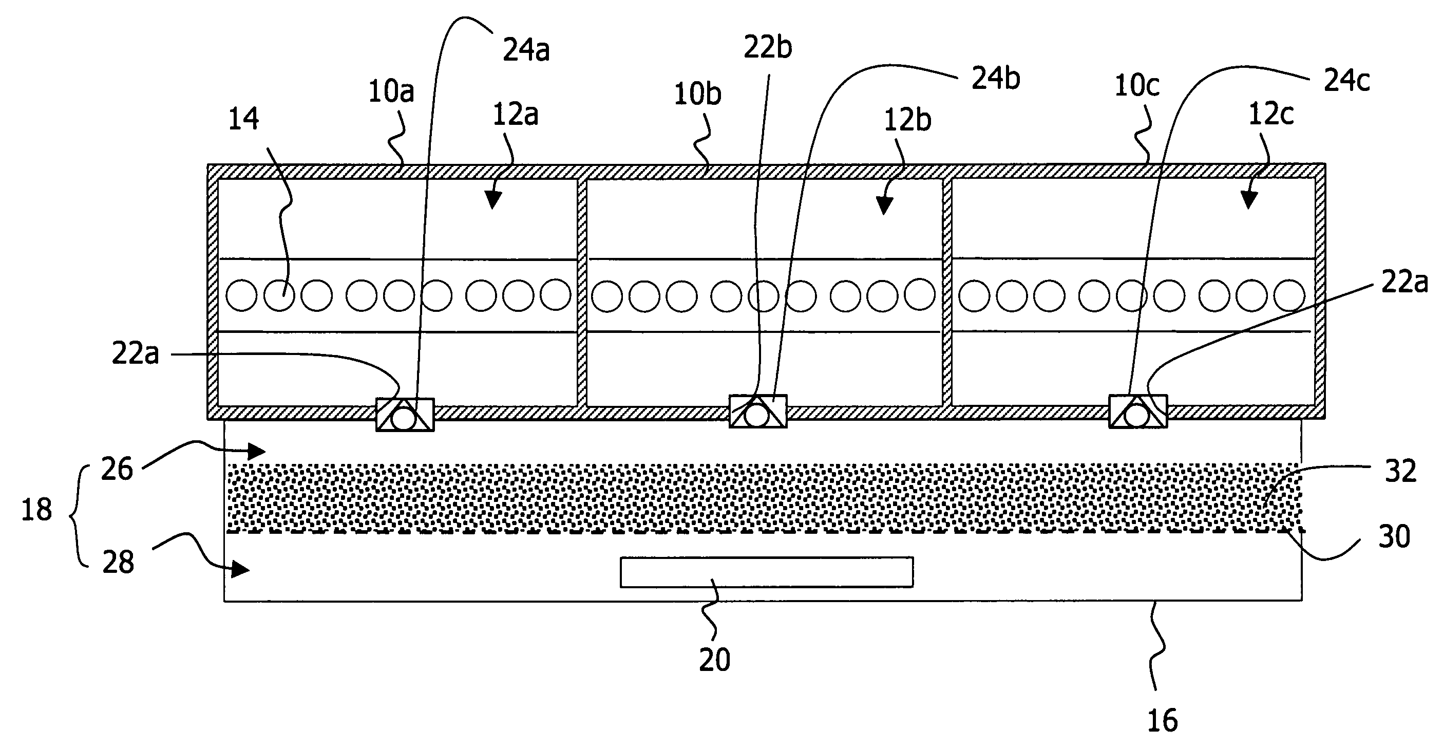
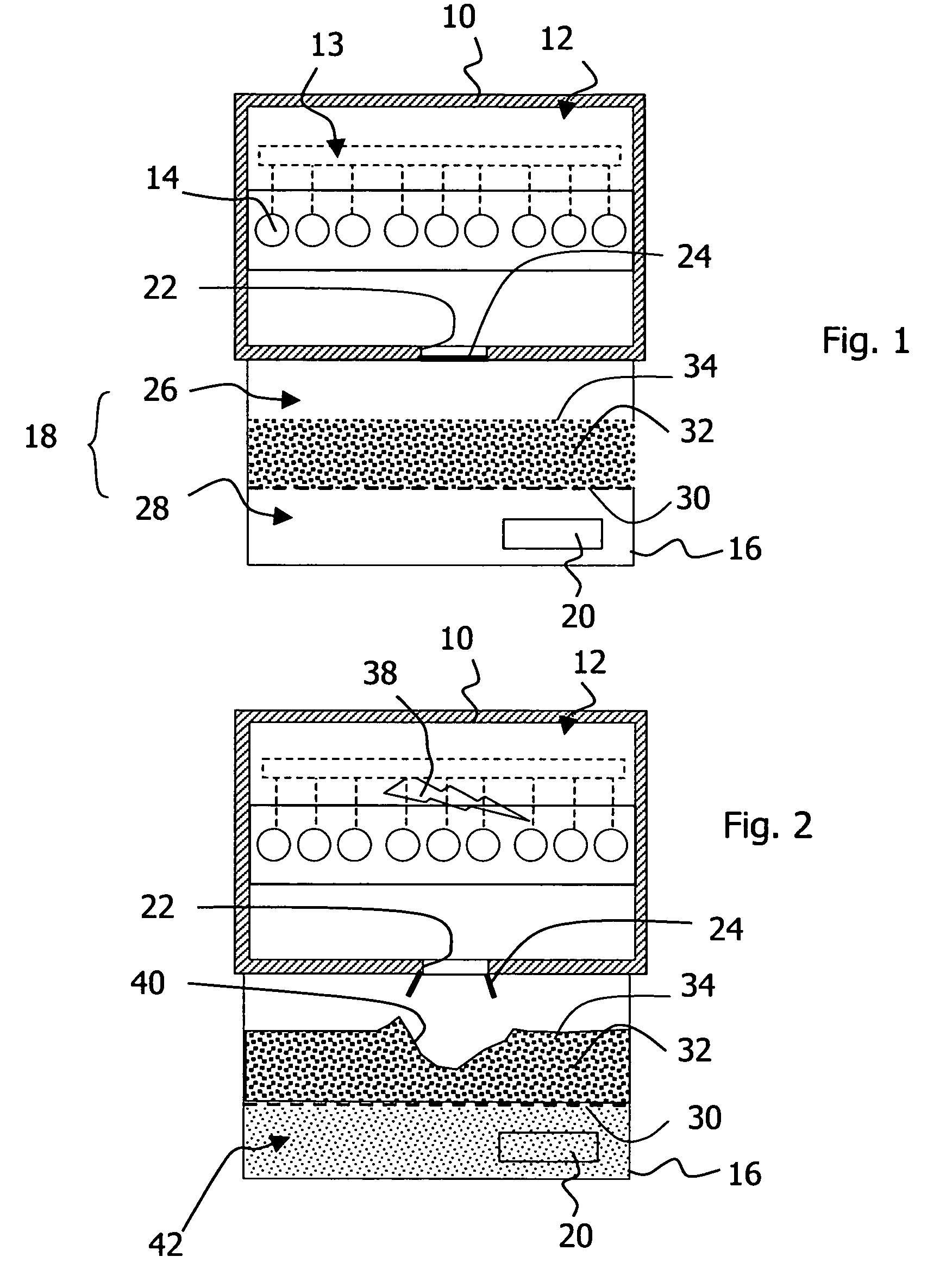
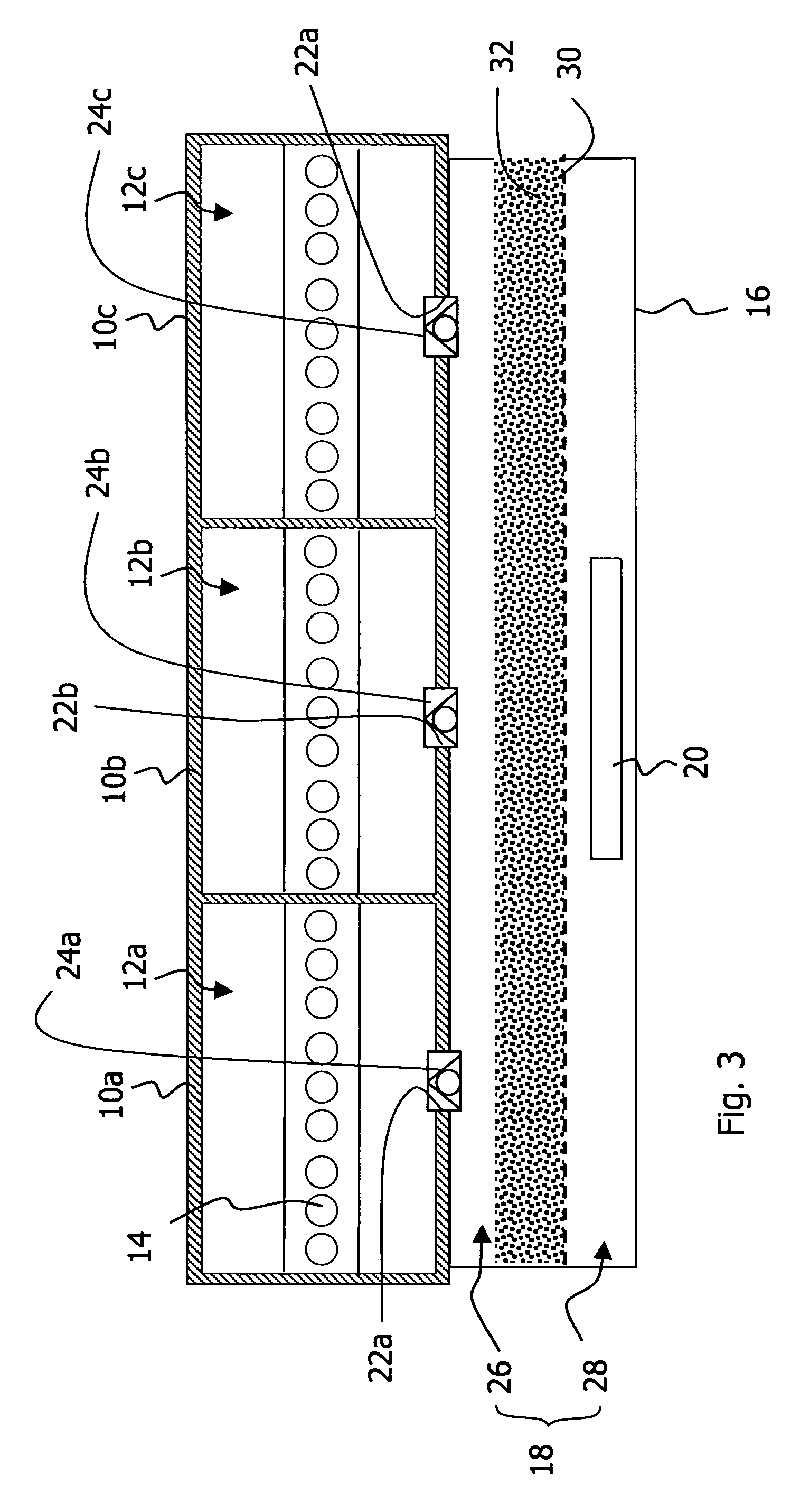
[0025]With reference to FIG. 1, a high-voltage electrical installation comprises a sealed enclosure 10 forming a containment 12 containing a high dielectric strength gas, for example sulphur hexafluoride, and housing a high-voltage functional unit 13, represented in schematic manner by a broken line in FIG. 1, comprising electrical conductors under high voltage, that may be connected to electrical apparatuses such as for example circuit breakers, disconnectors, earthing switches, cut-outs, switches, or distribution transformers or measuring auxiliaries and connected to the outside by means of bushings 14. This sealed enclosure 10 is arranged on a base 16 the walls whereof form, with a bottom wall of the enclosure, a cooling enclosure 18 provided at the bottom part with an escape outlet 20. The bottom wall of the containment 12 is provided with an outlet orifice 22 making the containment communicate with the cooling enclosure. In normal operation, this orifice 22 is closed by a membr...


PUM


Abstract

An electrical equipment containment is arranged on a cooling enclosure opening out onto the outside. An outlet orifice makes the containment communicate with the cooling enclosure. This orifice is closed by a membrane or a check valve. A grate separates the cooling enclosure into an upper volume and a lower volume. The grate supports a layer of solid granular material the upper surface whereof remains free. This material is preferably porous and also comprises dusts. In the event of an internal electric arc, the shock wave escaping from the containment is dampened by the surface deformation of the layer of solid material. The incandescent particles projected via the opening are stopped by the layer of solid material. The hot gases are cooled as they flow through the material, causing a cloud of dust contributing to preventing any post-combustion.

Description

BACKGROUND OF THE INVENTION[0001]The invention relates to an electrical installation comprising an enclosure wherein there are arranged conductors and, possibly, electrical apparatuses such as current breaking, measuring, switching or electrical transformation apparatuses. More particularly, but in non-exclusive manner, the invention relates to a high-voltage electrical installation with gas insulation. In the whole of the text, the term “high voltage” will be taken in its broadest sense as also including what is known in certain countries as the field of “medium voltage”.STATE OF THE PRIOR ART[0002]High-voltage electrical installations are subject to disfunctionings able to result in a short-circuit giving rise to an electric arc of very high energy. When the electrical installation comprises an enclosure, we refer to an internal arc to designate this uncontrolled arc. The internal arc gives rise to flows of hot gases, sometimes flammable or inflamed, at high pressure, preceded or ...

Claims


Application Information

Patent Timeline
Patent Type & Authority Patents(United States)
IPC IPC(8): H02H9/00H02B1/28H01H33/08H02B1/00H02B13/025H02B13/065
CPCH02B13/025H02B13/065
Inventor CHEVALLIER, PATRICKFAYE, JEAN-CLAUDEGENTILS, FRANCOISGIRAUD, STEPHANESERVE, DOMINIQUE
Owner SCHNEIDER ELECTRIC IND SAS
Why Eureka
Try Eureka