Check patentability & draft patents in minutes with Patsnap Eureka AI!

Guide roller arrangement for cranes

Active Publication Date: 2010-11-11
KONECRANES GLOBAL
View PDF5 Cites 3 Cited by
  • Summary
  • Abstract
  • Description
  • Claims
  • Application Information

AI Technical Summary

Benefits of technology

[0010]Another approach for achieving a very fine adjustment results from a similar design, wherein, however, the outside toothing of the axle carrier does not engage directly with the inside toothing of the securing plate. The two sets of teeth form an annular gap within which a ring is deposed that has teeth on both the inside and the outside. The outside toothing of the ring matches, for example, the inside toothing of the securing plate, while the inside teeth on the ring are an integer multiple of the outside teeth on the axle carrier. If the number of inside teeth on the ring and the number of outside teeth are also relatively prime, it is possible to achieve a type of vernier adjustment that allows a very fine adjustment. Thereby the adjustment of eccentricity in very fine increments becomes possible.
[0021]If a spacer plate is inserted between the securing plate and the carrier plate, it is possible to use longer fixation bolts, which is beneficial to the reliability of the threaded connection.

Problems solved by technology

That would result in a sliding friction that would cause the wheel flange or the rail head to wear prematurely.

Method used


Image

  • Guide roller arrangement for cranes
  • Guide roller arrangement for cranes
  • Guide roller arrangement for cranes

Examples


Embodiment Construction

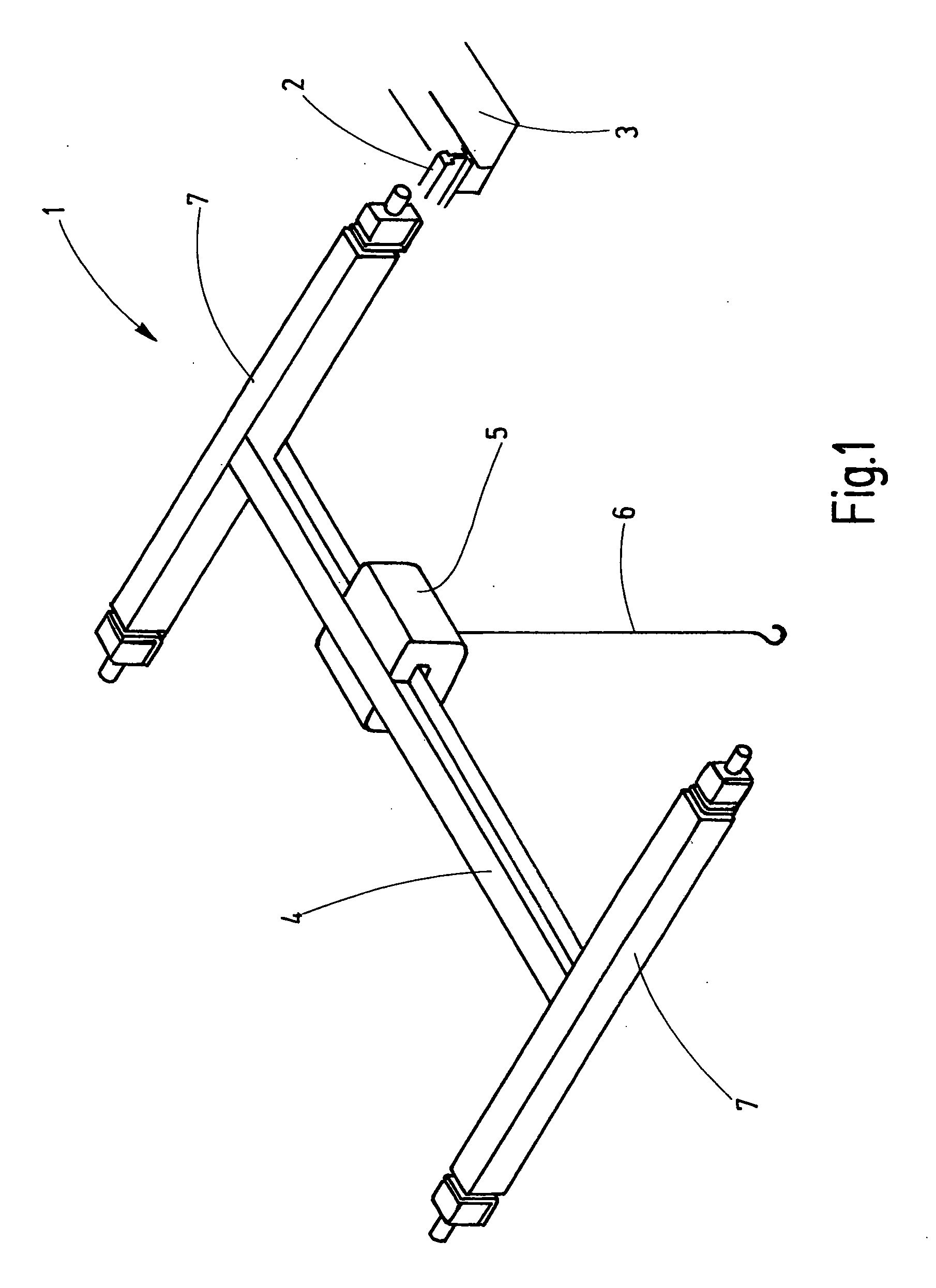
[0033]Referring more particularly to FIG. 1 of the drawings, there is shown an illustrative gantry crane 1 designed to travel along two crane track rails 2, one of which is shown. The crane track rails 2 are mounted parallel to one another, such as on trusses 3 of a building. The gantry crane 1 has a straight crane bridge 4 that is formed, for example, by a double T-beam. A crab 5 with lifting gear contained therein, from which a cable is suspended as a carrying means 6, travels along the crane bridge 4.

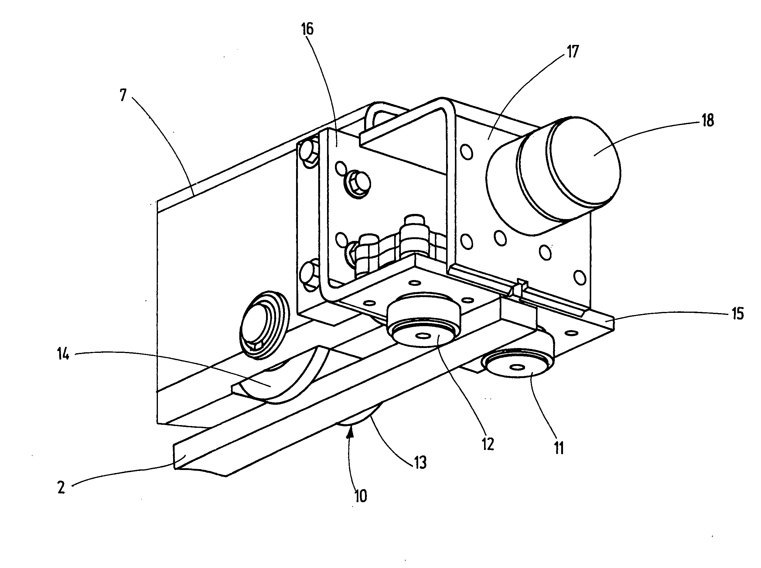
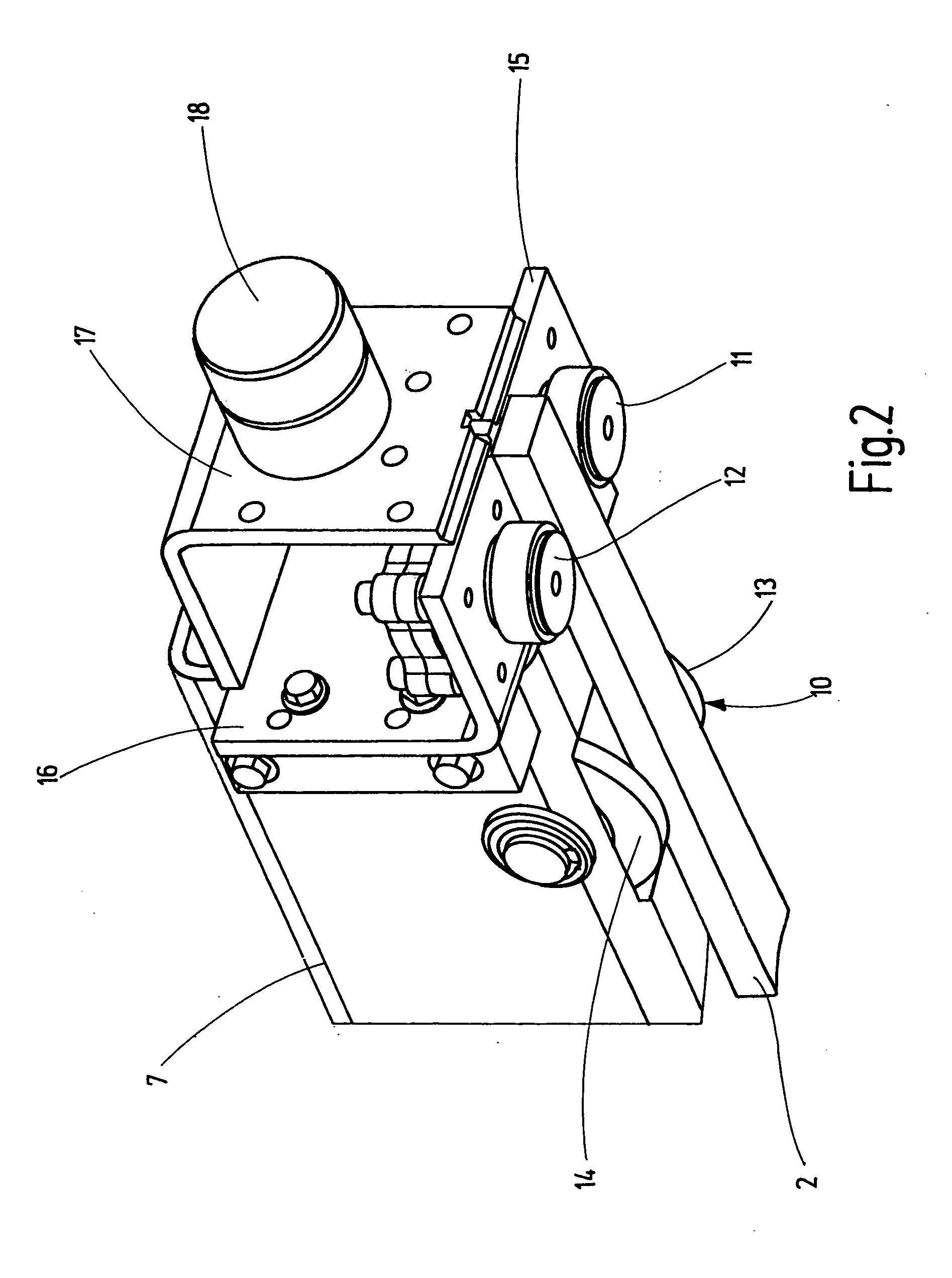
[0034]The ends of the crane bridge 4 are connected to two crane head carriers 7 provided at their ends with running rollers 10 and guide rollers 11, 12 (FIG. 2), with the aid of which the gantry crane 1 travels and is guided, respectively, on the crane track rails 2.

[0035]FIG. 2 shows one of the ends of a crane head carrier 7 in a perspective view from below on the crane track rail 2. The running roller 10 is rotatably seated in the tubular crane head carrier 7 and projects a distanc...


PUM


Abstract

A guide-roller arrangement for gantry cranes(1) has two rotatably mounted axial carriers (21) on which the guide rollers are seated. The guide rollers (11, 12) are mounted on journals which are arranged in the carrier plate (15) in a manner eccentric to the axis of rotation (41) of the axial carrier (21). The selected eccentric position of the journal can be fixed in a formfitting manner with the aid of toothing formations (29, 36) on the axial carrier and on the carrier plate.

Description

CROSS-REFERENCE TO RELATED APPLICATIONS[0001]This patent application is the national phase of PCT / EP2008 / 009648, filed Nov. 14, 2008, which claims the benefit of German Patent Application No. 102007054693.0, filed Nov. 14, 2007.FIELD OF THE INVENTION[0002]The present invention relates generally to gantry cranes, and more particularly, to an improved guide roller arrangement for guiding movement of the carrier head of the gantry crane along transport rails.BACKGROUND OF THE INVENTION[0003]Gantry cranes run on parallel crane rails that are installed along the ends of the crane bridge. The crane bridge runs between two mutually parallel crane head carriers on which the crane wheels are rotatably seated. A distinction is made between the crane wheels, which absorb the load and are therefore the actual crane wheels, and guide rollers, which hold the crane head carriers on the rail. Out of concern for wear on the rail head, the lateral guidance should not be performed via the crane wheel,...

Claims


Application Information

Patent Timeline
IPC IPC(8): B66C9/16B66C9/00B66C19/00
CPCF16C29/12B66C9/16F16C2326/00
Inventor GOLDER, MARCUS
Owner KONECRANES GLOBAL
Features
  • R&D
  • Intellectual Property
  • Life Sciences
  • Materials
  • Tech Scout
  • Unparalleled Data Quality
  • Higher Quality Content
  • 60% Fewer Hallucinations
Learn More