Method and apparatus for optimal nock travel for a compound archery bow

a compound bow and nock travel technology, applied in the field of compound bows, can solve the problems of cam(s) tilting, angular lateral displacement of the bow string, deviation from the natural travel path, etc., and achieve the effect of quick reduction of cable offs

Inactive Publication Date: 2010-11-11
MARZULLO JOSEPH H
View PDF20 Cites 30 Cited by
  • Summary
  • Abstract
  • Description
  • Claims
  • Application Information

AI Technical Summary

Benefits of technology

[0021]An object of the present invention is to provide an improved method and apparatus for providing fletching clearance as the arrow's fletching approaches the cables, and quickly reducing the cable offset during the rest of the shot.
[0031]As the bowstring is drawn rearward by a bow user during operation, the top and bottom limbs of the compound bow flex rearward causing the cam(s) to rotate, thus shifting the first and second cables, and causing the cable guard slide to move in a downward path along the proximal portion of the cable guard rod.
[0033]A further set of steps of the method include: drawing a bowstring connected at one end to the upper limb of the compound bow and at the opposite end to the lower limb of the compound bow, and causing the upper limb and the lower limb to flex rearward; and, rotating at least one cam, so as to shift the first and second cables, and causing the cable guard slide to move in a downward path along the proximal portion of the cable guard rod. From that point, the method includes releasing the bowstring to propel the bowstring and the arrow forward and causing the first and second cables to move forward; and, in turn, moving the cable slide upward along the cable guard rod to allow the arrow to move forward without making contact with the cable slide. This insures correction of the angular nock travel 24 of the compound bow by the angular movement of the cable slide, thus substantially eliminating cam tilt.

Problems solved by technology

Deviation from the natural travel path degrades accuracy.
These high loads imposed off center on the cams create a very large load imbalance (see FIG. 11A) which causes the cam(s) to tilt.
The combined effect of the cable guard offset and increasing cable loads results in a cam tilt that produces an angular lateral displacement of the bow string during the bow's draw cycle.
It causes the bow to twist in the archer's hand and results in undesirable “angular nocking point / bow string travel”.
Although only a few degrees in bow rotation, torque is undesirable as it causes the arrow to fly to left for right handed archers, and to the right for left handed archers.
This is detrimental to the archer achieving accurate and consistent arrow flight.
What is not appreciated by the prior art are problems created by the cables being offset to provide fletching clearance, the unintended consequence of which is cam tilt.

Method used


Image

  • Method and apparatus for optimal nock travel for a compound archery bow
  • Method and apparatus for optimal nock travel for a compound archery bow
  • Method and apparatus for optimal nock travel for a compound archery bow

Examples


second embodiment

[0055]Turning next to FIG. 9, there is shown a top view of the cable guard rod of the present invention.

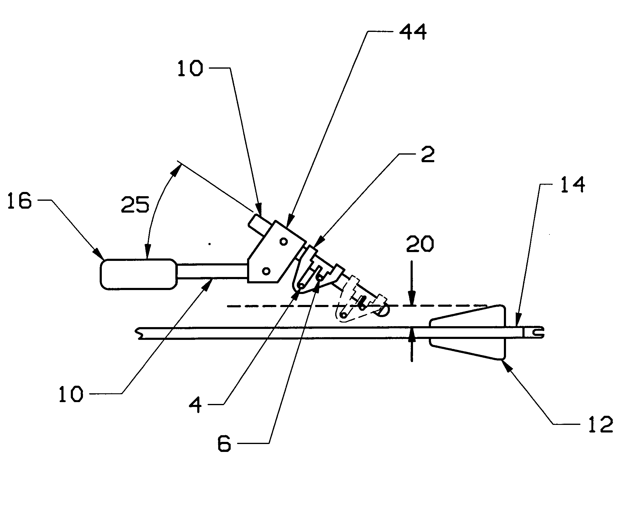
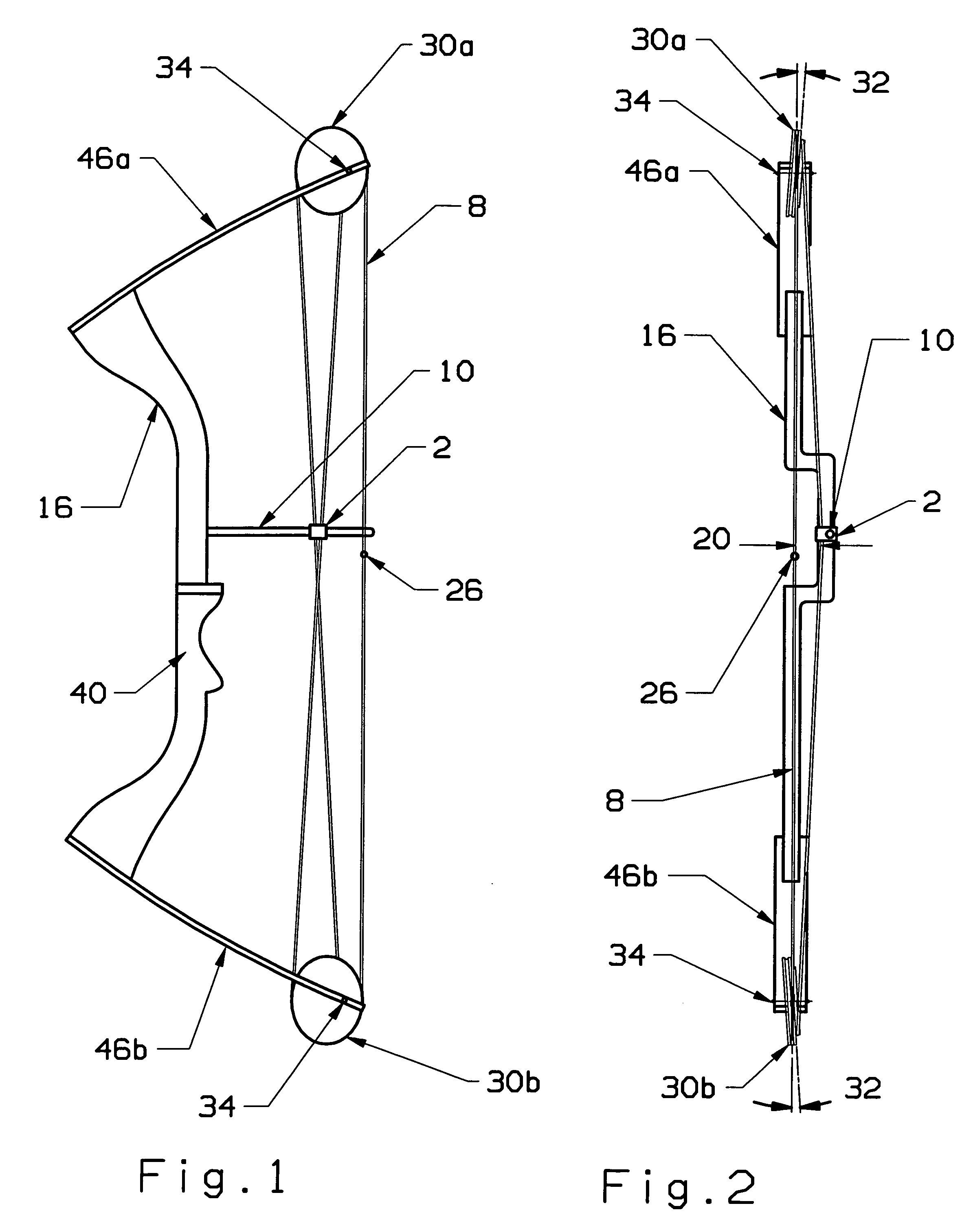
[0056]The cable guard rod 10 is preferably a single piece which is mounted to the bow's riser 16. The cable guard rod 10 can be made of any material suitable to the purpose, though a preferred embodiment would be the use of aluminum or a composite. The bow's cables 4, 6 are located in a cable slide 2 which slides on the cable guard rod 10. The cable slide 2 has a means of locating and trapping the bow's cables to prevent them from contacting each other during normal operation. The cable slide 2 must move laterally approximately 0.6″ towards the arrow 14 within the rearward / forward motion determined by the cable's 4, 6 movement so as to provide clearance 20 for the fletching 12.

[0057]There is created an exterior angle 25 from the upper portion of the cable guard rod 10 to the lower portion of the cable guard rod. The lower portion of the cable guard rod 10 is essentially perpendicu...

third embodiment

[0059]With reference next to FIG. 10, there is shown a top view of the cable guard rod of the present invention.

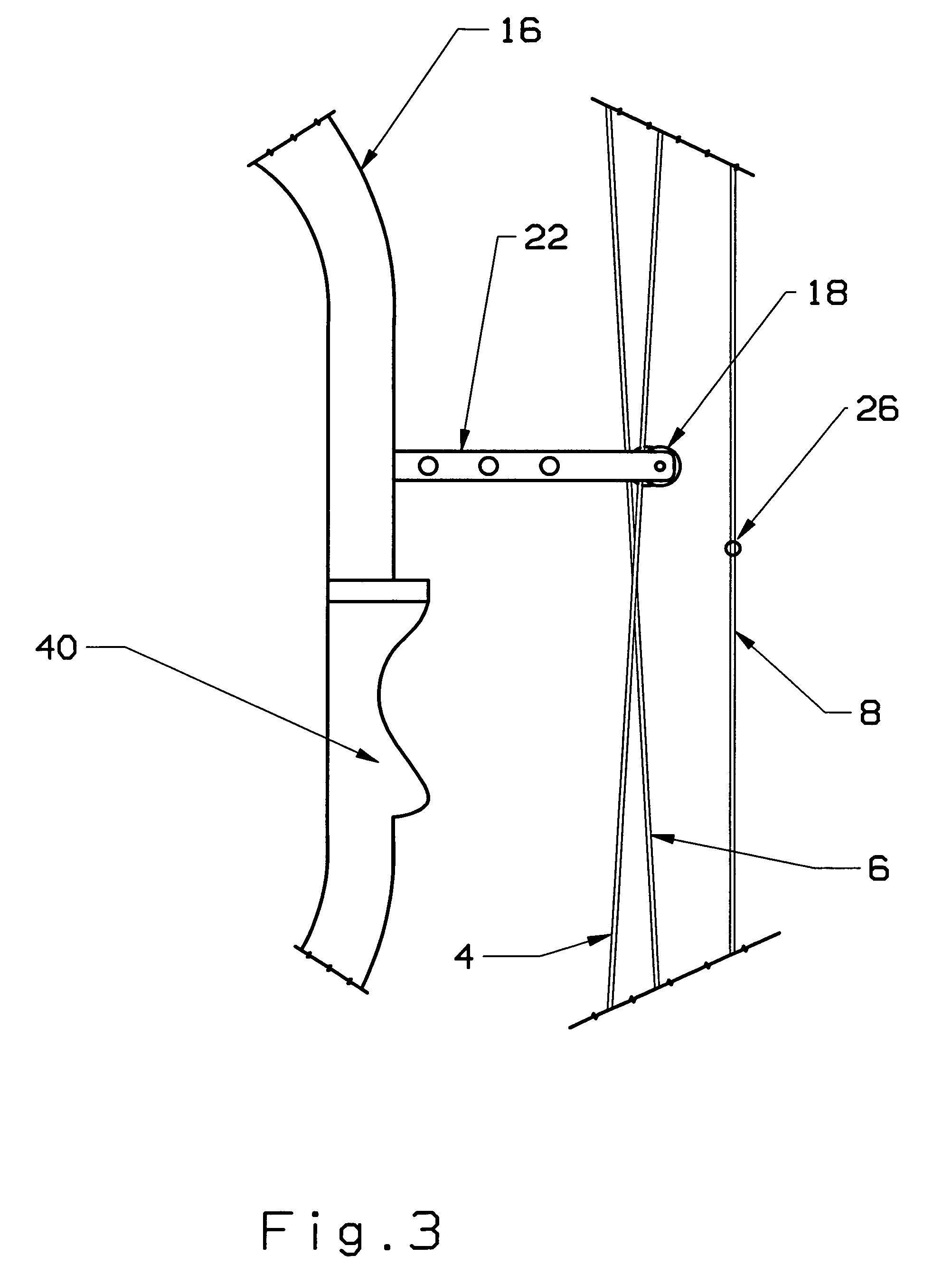
[0060]The cable guard rod 10 / block 44 is mounted, either directly or indirectly, to the bow's riser 16 of the frame. The cable guard rod 10 is comprised of two parts (an upper half and a lower half) and its corresponding block 44. The cable guard rod 10 and bracket 22 can be made of any material suitable to the purpose, though a preferred embodiment would be the use of aluminum or a composite. The bow's cables 4, 6 are located in a cable slide 2 which slides on the cable guard rod 10. The sliding block 2 has a means of locating and trapping the bow's cables to prevent them from contacting each other during normal operation. The cable slide 2 must move laterally approximately 0.6″ towards the arrow 14 within the rearward / forward motion determined by the cable's 4, 6 movement.

[0061]There is created an exterior angle 25 from the upper portion of the cable guard rod 10 to the ...


PUM


Abstract

The invention is a method and apparatus for correcting the natural nock travel of a compound bow. The bow has a cable guard rod attached to a riser supporting a cable slide at an angle to the nock travel path. The rod has a distal portion attached to the riser, a central portion angled upward relative to the distal portion, and, a proximal portion angled downward so as to form an exterior angle falling within the range of 25-40° between the proximal and distal portions of the cable guard rod. The bow has a cam mounted on an upper limb, a cam mounted on a lower limb, and two cables which are connected to the first cam, pass through the cable slide, and are connected to the second cam. There is also a bow string connected between the cams which can be drawn rearward then released to provide energy.

Description

BACKGROUND OF THE INVENTION[0001]1. Field of the Invention[0002]The present invention relates to a method and apparatus for a compound archery bow of a type used for hunting, target shooting, or related activities. More specifically, the present invention relates to a method and system for stabilizing the nock point travel of a compound bow so as to optimize the bow's accuracy while reducing wear on cables caused by cam tilt forces.[0003]2. Description of the Related Art[0004]Compound archery bows, such as that shown in FIG. 1, generally provide a number of benefits over traditional bows (also known as long bows). They store a lot more energy due to the profiles of the cams which flex the limbs while the bow is drawn. This results in an arrow that is shot with higher velocity and more energy. They also provide another important benefit over traditional bows, in that when the bow is drawn to its maximum point, the cams provide a mechanical advantage to the archer that reduces the hol...

Claims


Application Information

Patent Timeline
Patent Type & Authority Applications(United States)
IPC IPC(8): F41B5/10F41B5/14
CPCF41B5/14F41B5/10
Inventor MARZULLO, JOSEPH H.
Owner MARZULLO JOSEPH H
Why Eureka
Try Eureka