Oil pressure control in an engine

a technology of oil pressure control and engine, which is applied in the direction of pump control, positive displacement liquid engine, machines/engines, etc., can solve the problems of rapid reduction of oil pressure in the galleries and subsequent restart of the engine without the necessary oil

Active Publication Date: 2010-11-11
GM GLOBAL TECH OPERATIONS LLC
View PDF9 Cites 8 Cited by
  • Summary
  • Abstract
  • Description
  • Claims
  • Application Information

AI Technical Summary

Benefits of technology

[0005]In view of the foregoing, an engine having a fluid lubrication and control system is provided. The engine includes a pump configured to maintain fluid pressure in the lubrication and control system when the engine is running. The engine also includes an accumulator in fluid communication with the lubrication and control system. The accumulator is configured to accumulate and retain fluid when the engine is running, and to discharge the fluid when the engine is not running in order to maintain fluid pressure in the lubrication and control system. The fluid lubrication and control system may include a camshaft phaser operable by fluid pressure, wherein the accumulator is configured to maintain fluid pressure to the phaser when engine is shut-off.

Problems solved by technology

When the engine is shut-off, the oil pump ceases to operate, and oil pressure in the galleries rapidly diminishes.
Because oil pressure requires time to be reestablished, a subsequent restart of the engine is affected without the necessary oil pressure.

Method used


Image

  • Oil pressure control in an engine
  • Oil pressure control in an engine
  • Oil pressure control in an engine

Examples


Embodiment Construction

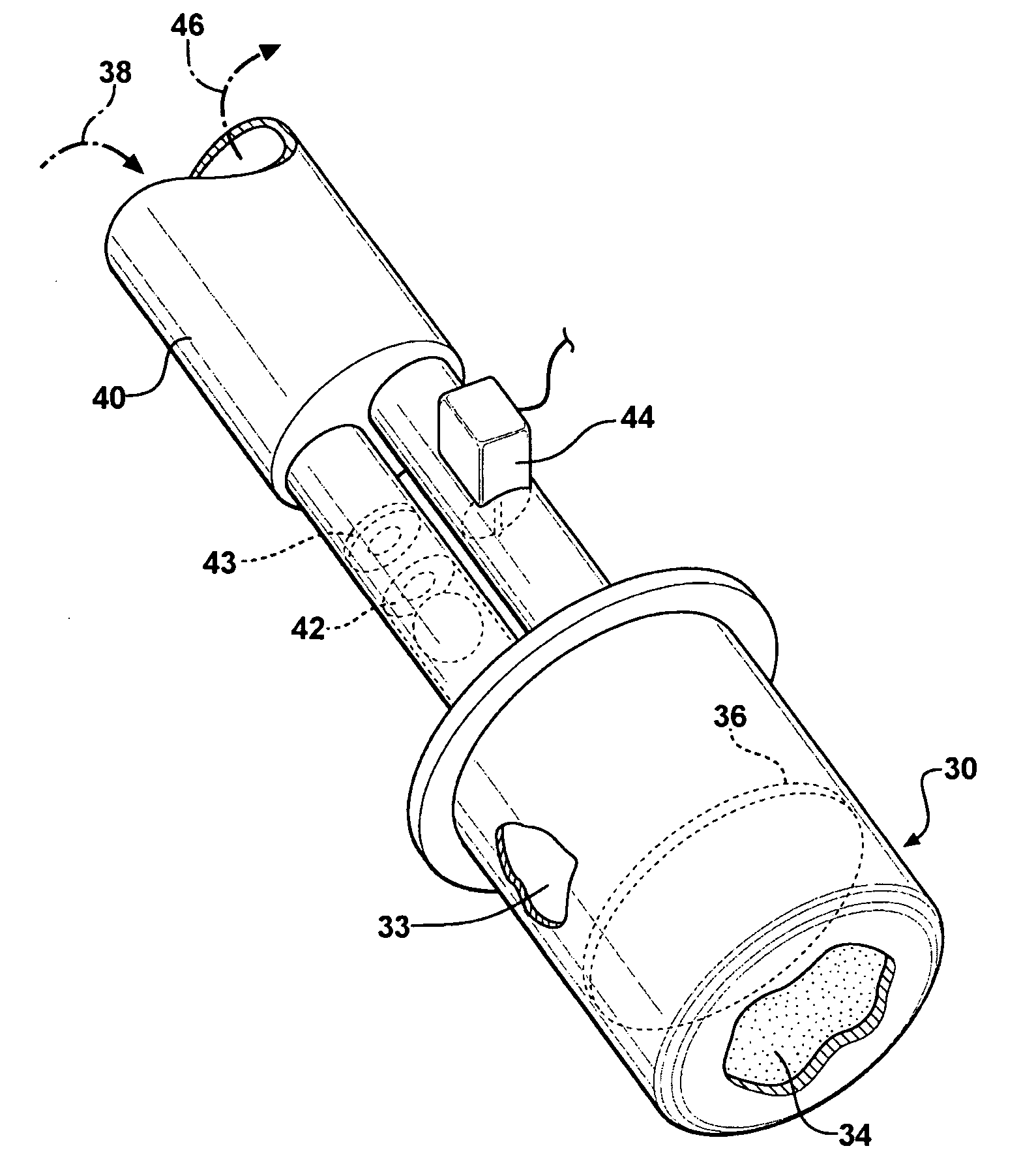
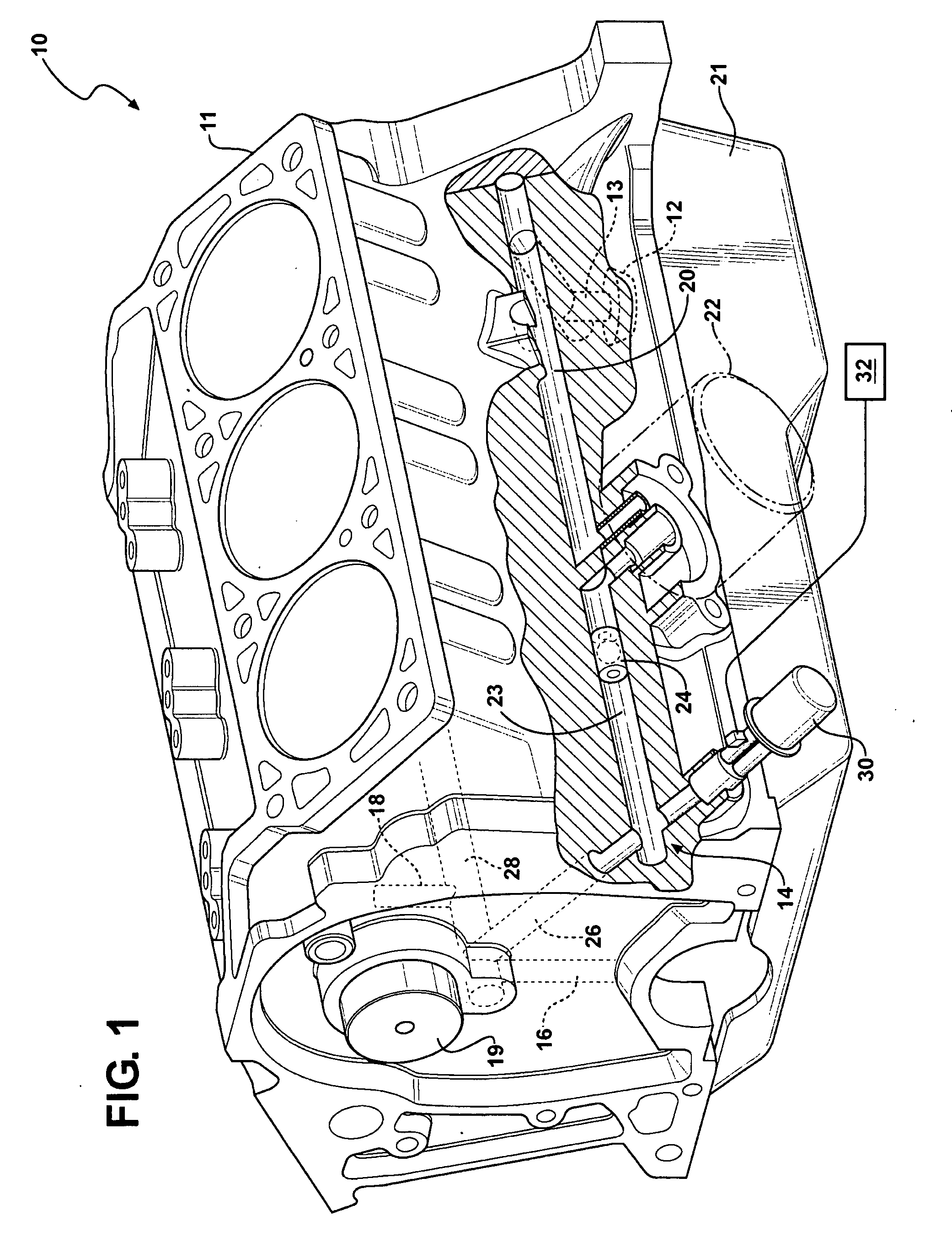
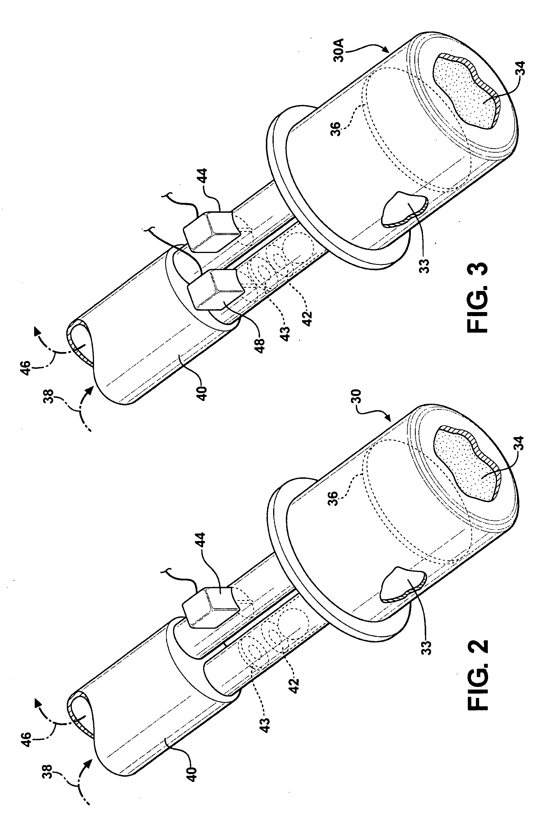
[0015]Referring to the drawings in which like elements are identified with identical numerals throughout, FIG. 1 shows an engine 10 inclusive of an engine block 11 and an oil pan 21. The engine 10 includes an oil pump 12 and a fluid lubrication and control system 14. The pump 12 is driven mechanically by a crankshaft (not shown) of the engine 10, to maintain oil pressure to the fluid lubrication and control system 14 via a passage 13, when the engine is running. The fluid lubrication and control system 14 includes multiple oil passages strategically routed throughout the engine 10 for effective cooling, lubrication and control of engine components, as understood by those skilled in the art. The fluid lubrication and control system 14 includes passages 16 for feeding crankshaft bearings (not shown), and passages 18 for feeding camshaft bearings (not shown) and for supplying oil to a camshaft phaser 19. As understood by those skilled in the art, a camshaft phaser 19 is a mechanism emp...


PUM


Abstract

An engine having a fluid lubrication and control system is provided. The engine also includes a pump configured to maintain fluid pressure in the lubrication and control system when the engine is running. The engine additionally includes an accumulator in fluid communication with the lubrication and control system. The accumulator is configured to accumulate and retain fluid when the engine is running, and to discharge the fluid when the engine is not running in order to maintain fluid pressure in the lubrication and control system. A method for controlling oil pressure in the engine is also provided.

Description

TECHNICAL FIELD[0001]The present invention relates to control of oil pressure, and, more particularly, to controlling oil pressure in an engine of a motor vehicle.BACKGROUND OF THE INVENTION[0002]A typical internal combustion engine, as employed in vehicle propulsion systems, requires a circulation of pressurized fluid or oil through specially configured galleries to provide cooling and lubrication to components such as bearings and piston rings. Lubrication is generally employed to prevent physical contact between neighboring surfaces experiencing motion relative to one another. Oil pressure is also utilized to control various components, such as, for example, a camshaft phaser.[0003]Pressurized engine oil is typically supplied by an oil pump driven mechanically by the engine's crankshaft. When the engine is shut-off, the oil pump ceases to operate, and oil pressure in the galleries rapidly diminishes. Because oil pressure requires time to be reestablished, a subsequent restart of ...

Claims


Application Information

Patent Timeline
Patent Type & Authority Applications(United States)
IPC IPC(8): F04B49/10F01M9/00
CPCF01M5/025F01M1/16
Inventor REYNOLDS, MICHAEL G.PRYOR, BRYAN K.ALBERTSON, WILLIAM C.MC DONALD, MIKE M.
Owner GM GLOBAL TECH OPERATIONS LLC
Why Eureka
Try Eureka