
High-pressure power cable connector

a technology of high-pressure power cables and connectors, which is applied in the direction of cable junctions, connection contact materials, coupling devices, etc., can solve the problems of premature breakdown, inability to achieve the original anticipated longevity of 30 to 40 years, and high cost and involved procedures, so as to eliminate the pushback of the insulation jacket

Active Publication Date: 2005-09-01
NOVINIUM LLC
View PDF67 Cites 64 Cited by
  • Summary
  • Abstract
  • Description
  • Claims
  • Application Information

AI Technical Summary

Benefits of technology

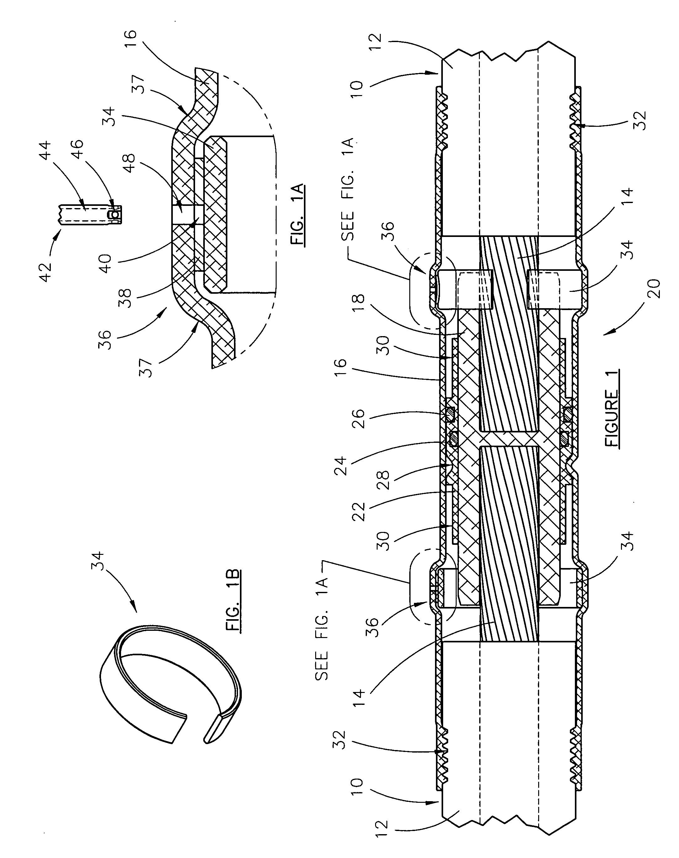
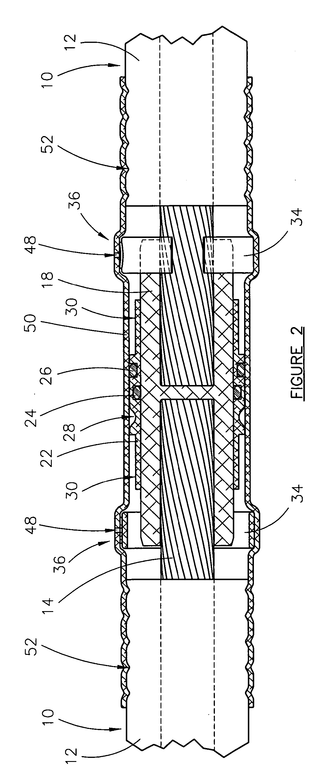
[0012] The high-pressure terminal or splice connectors contemplated in the instant application address the above mentioned problems and are designed to inject a dielectric-enhancing fluid (e.g., a tree retardant fluid) into the interstitial void volume of an electrical cable segment at a high pressure and confine the fluid therein at a similarly high, sustained residual pressure. Alternatively, the instant device can be a high-pressure splice connector used in a flow-though mode wherein injection of fluid takes place at a remote point of the cable segment. Furthermore, the instant high-pressure connectors allow residual fluid pressure to be maintained in the interstitial void volume of the cable while essentially eliminating pushback of the insulation jacket.
[0016] In some embodiments the housing has an end portion with the housing wall thereof sized to receive at least a portion of the stranded conductor within the housing interior chamber with the cable segment extending from the housing end portion. An attachment means is provided for sealing the insulation jacket with respect to the housing wall and confining the fluid at the residual pressure within the housing interior chamber and the interstitial void volume, and for sufficiently securing the cable segment to the housing to prevent pushback of the insulation jacket at the residual pressure.
[0023] A first securing member is configured to secure the first cable segment to the housing at the first end portion of the housing to prevent pushback of the first insulation jacket at the first residual pressure, and a second securing member is configured to secure the second cable segment to the housing at the second end portion of the housing to prevent pushback of the second insulation jacket at the second residual pressure.

Problems solved by technology

Unfortunately, these cables, particularly those installed prior to 1985, which generally comprise a stranded conductor surrounded by a semi-conducting shield, a polymeric insulation jacket, and an insulation shield, often suffer premature breakdown and do not attain their originally anticipated longevity of 30 to 40 years.
Since replacing a failed section of underground cable can be a very costly and involved procedure, there is a strong motivation on the part of the electrical utility industry to extend the useful life of existing underground cables in a cost-effective manner.
This method and variations thereof employing certain rapidly diffusing components (see U.S. Pat. Nos. 5,372,840 and 5,372,841) have enjoyed commercial success over the last decade or so, but they still have some practical limitations when reclaiming underground residential distribution (URD) cables, which have a relatively small diameter, and therefore present insufficient interstitial volume relative to the amount of retardant required for optimum dielectric performance.
These repetitive trips are costly in terms of human resource.
Moreover, even when higher pressures were maintained in an experimental determination of possible detrimental effects of excessive pressure, a maximum pressure of 117 psig was maintained for only two hours.

Method used


Image

  • High-pressure power cable connector
  • High-pressure power cable connector
  • High-pressure power cable connector

Examples


examples

[0093] An electric distribution cable (I / O, 15 kV, 100%, concentric; 107 feet in length) was coiled and immersed in a water bath at 30° C. The ends of the cable were each prepared with a nominal ⅛″ to ¼″ gap between crimped pin terminators and the insulation jacket cut-back to accommodate the flow of fluid into the cable stands. A terminal connector, as shown in FIG. 11, but with collar 230 omitted, was installed over each cable end. The cable was filled with acetophenone at a uniform pressure of 30 psig and maintained for seven days. On the seventh day, the pressure was uniformly increased and held at approximately 60 psig. On the eleventh day of the experiment the pressure was uniformly increased to 120 psig. A leak was detected and depressurization was observed on the twelfth day of the experiment and after 27.5 hours at 120 psig. The leak was caused by pushback of the insulation jacket at one end past the seal at the cable-side of the terminal connector. The amount of pushback d...


PUM


Abstract

A high-pressure connector for an electrical power cable segment having a central stranded conductor encased in a polymeric insulation jacket with an interstitial void volume in the region of the conductor. The connector confines a fluid within the interstitial void volume at a residual pressure above atmospheric, but below the elastic limit of the insulation jacket. A housing interior chamber receives the conductor in fluid communication with the interstitial void volume. Some embodiments have the chamber sized to receive and overlap a portion of the insulation jacket with a housing end portion swaged thereto. A seal seals the insulation jacket with respect to the housing and a retaining member secures the cable segment to the housing to prevent pushback of the insulation jacket at the residual pressure.

Description

BACKGROUND OF THE INVENTION [0001] 1. Field of the Invention [0002] The present invention relates to a connector suitable for injecting a dielectric enhancement fluid into the interstitial void volume of an electrical cable segment. More particularly, the invention relates to a high-pressure terminal connector and a high-pressure splice connector adapted for injecting the fluid at an elevated pressure and then confining the fluid within the void volume at a residual pressure, wherein pushback of the insulation jacket of the cable is essentially eliminated. [0003] 2. Description of the Related Art [0004] Extensive networks of underground electrical cables are in place in many parts of the industrialized world. Such underground distribution offers great advantage over conventional overhead lines in that it is not subject to wind, ice or lightning damage. It is therefore viewed as a reliable means for delivering electrical power without obstructing the surrounding landscape, the latter...

Claims


Application Information

Patent Timeline
Patent Type & Authority Applications(United States)
IPC IPC(8): H01R13/523H01R13/533H01R24/00
CPCH01R13/523H02G15/18H01R13/533H02G15/22H02G15/24H01R4/64
Inventor BERTINI, GLEN JOHNTHEIMER, ANTHONY ROY
Owner NOVINIUM LLC
Learn More