Control apparatus of automatic transmission

a control apparatus and automatic transmission technology, applied in mechanical apparatus, clutches, instruments, etc., can solve the problems of preventing the improvement of fuel consumption of the vehicle, revving up the engine, etc., to improve fuel consumption and ride comfort of the vehicle, prevent the delay in the engagement of the lock-up clutch, and prevent the effect of revving up the driving source immediately after the star

Inactive Publication Date: 2011-10-06
AISIN AW CO LTD
View PDF9 Cites 18 Cited by
  • Summary
  • Abstract
  • Description
  • Claims
  • Application Information

AI Technical Summary

Benefits of technology

[0007]Thus, it is an object of the present invention to provide a control apparatus of an automatic transmission that enables a vehicle to start while preventing an occurrence of revving up of a driving source and a shake-back shock, and is thereby capable of improving fuel consumption and ride comfort of the vehicle.
[0008]According to a first aspect of the present invention, a clutch control unit controls a clutch to be disengaged to place an automatic speed change mechanism in a neutral state while a shift range is determined to be a drive range and a vehicle is determined to be stopped, and performs engagement control of the clutch to control a start of the vehicle when an operation intended for starting the vehicle is detected. On the other hand, a lock-up clutch control unit controls a lock-up clutch to be engaged in the state in which the shift range is determined to be the drive range and the vehicle is determined to be stopped (that is, in the neutral state of the clutch), and controls the lock-up clutch so that the lock-up clutch is at least engaged in a slip region in which a predetermined torque capacity is obtained, when the operation intended for starting the vehicle is detected. That is, the lock-up clutch is engaged before the start of the vehicle. Therefore, the lock-up clutch can be promptly engaged in the slip region even immediately after the start (delay in the engagement of the lock-up clutch can be prevented). Thus, revving up of the driving source immediately after the start can be prevented, whereby fuel consumption of the vehicle can be improved. In addition, while a rotation speed of the driving source is low, an output torque required by a driver is small and the lock-up clutch receives a smaller torque than the predetermined torque capacity. Therefore, the lock-up clutch is stably held in the engaged state, thereby making it possible to start the vehicle without an occurrence of shake-back shock and to improve ride comfort.
[0009]According to a second aspect of the present invention, if an output torque of the driving source and a torque capacity of the clutch are smaller than the predetermined torque capacity of the lock-up clutch, the vehicle is started while slip-controlling the clutch with the lock-up clutch engaged. Therefore, for example, if the required torque required by the driver is small, the lock-up clutch does not slip as described above, thus making it possible to prevent the revving up of the driving source, and to improve the fuel consumption of the vehicle.
[0010]According to a third aspect of the present invention, if the output torque of the driving source and the torque capacity of the clutch are larger than the predetermined torque capacity of the lock-up clutch, the vehicle is started by using a torque amplifying function of a torque converter while slipping the lock-up clutch. Therefore, for example, if the required torque required by the driver is small, the lock-up clutch does not slip as described above, thus making it possible to prevent the revving up of the driving source, and to improve the fuel consumption of the vehicle. In addition, for example, if the required torque required by the driver is large, a large output torque can be obtained, thereby making it possible to ensure driveability.
[0011]According to a fourth aspect of the present invention, if the output torque of the driving source and the torque capacity of the clutch are larger than the predetermined torque capacity of the lock-up clutch, the vehicle is started by using the torque amplifying function of the torque converter while releasing the lock-up clutch by the lock-up clutch control unit. Therefore, for example, if the required torque required by the driver is small, the lock-up clutch does not slip as described above, thus making it possible to prevent the revving up of the driving source, and to improve the fuel consumption of the vehicle. In addition, for example, if the required torque required by the driver is large, a large output torque can be obtained, thereby making it possible to ensure driveability. In addition, because the lock-up clutch is released without being slipped when starting the vehicle by using the torque amplifying function of the torque converter, drag by the lock-up clutch can be eliminated, whereby a larger torque amplifying function can be obtained.
[0012]According to a fifth aspect of the present invention, the lock-up clutch control unit controls the release, the slip, and the engagement of the lock-up clutch by referring to a lock-up control map based on the required output and a vehicle speed. Therefore, the engagement state of the lock-up clutch can be controlled without conducting complicated calculations. In addition, because a release region of the lock-up clutch corresponds to the state in which the output torque of the driving source and the torque capacity of the clutch are larger than the predetermined torque capacity of the lock-up clutch, the vehicle can be started by using the torque amplifying function of the torque converter in the released state of the lock-up clutch.

Problems solved by technology

However, because the lock-up clutch has been released when the vehicle starts, the vehicle is started while the torque converter slips, thus revving up the engine.
There is a problem that the revving up of the engine at the vehicle start prevents improvement in fuel consumption of the vehicle.

Method used


Image

  • Control apparatus of automatic transmission
  • Control apparatus of automatic transmission
  • Control apparatus of automatic transmission

Examples


Embodiment Construction

[0030]An embodiment according to the present invention will be described below with reference to FIGS. 1 to 17.

[0031][Outline of Automatic Transmission]

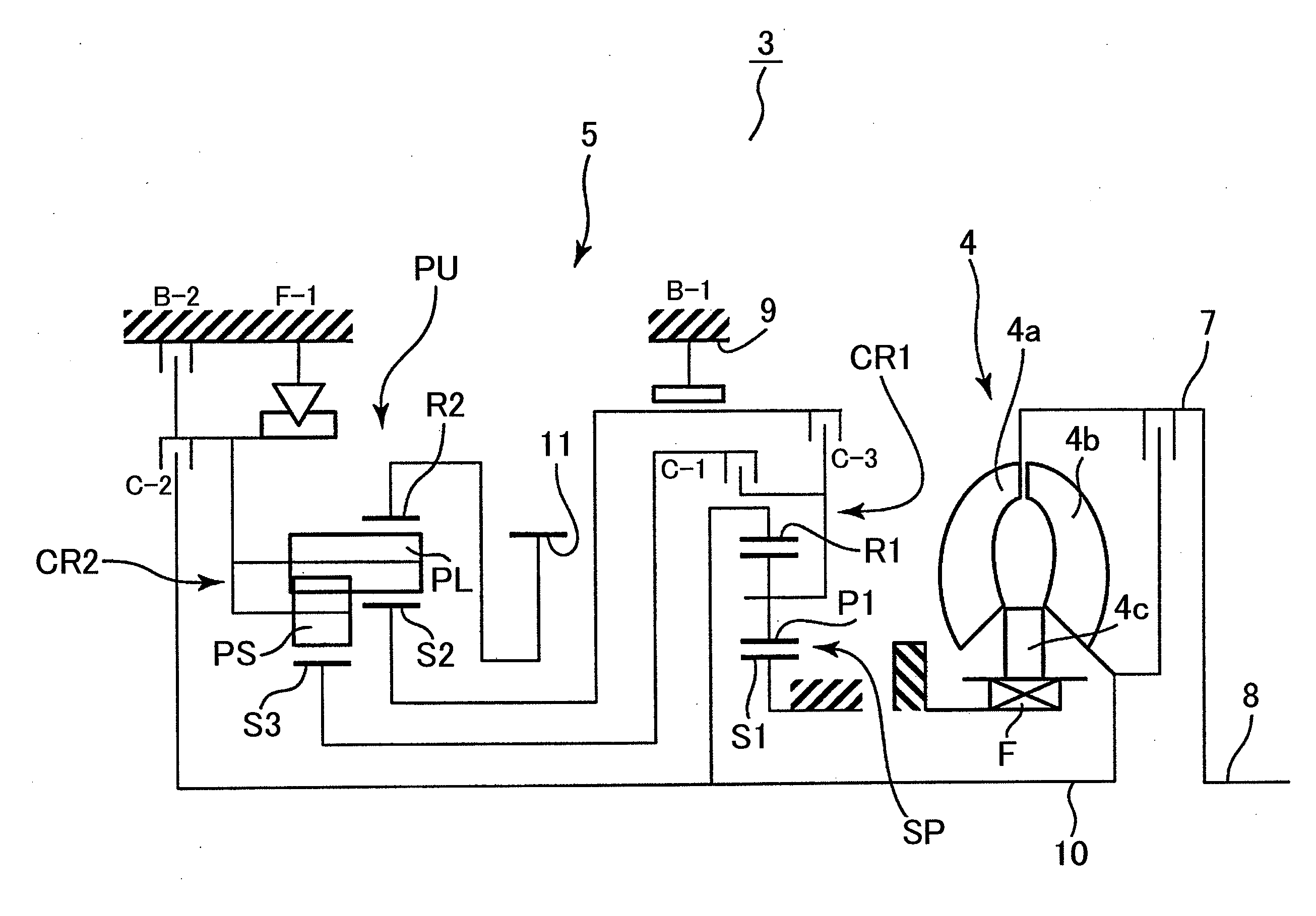
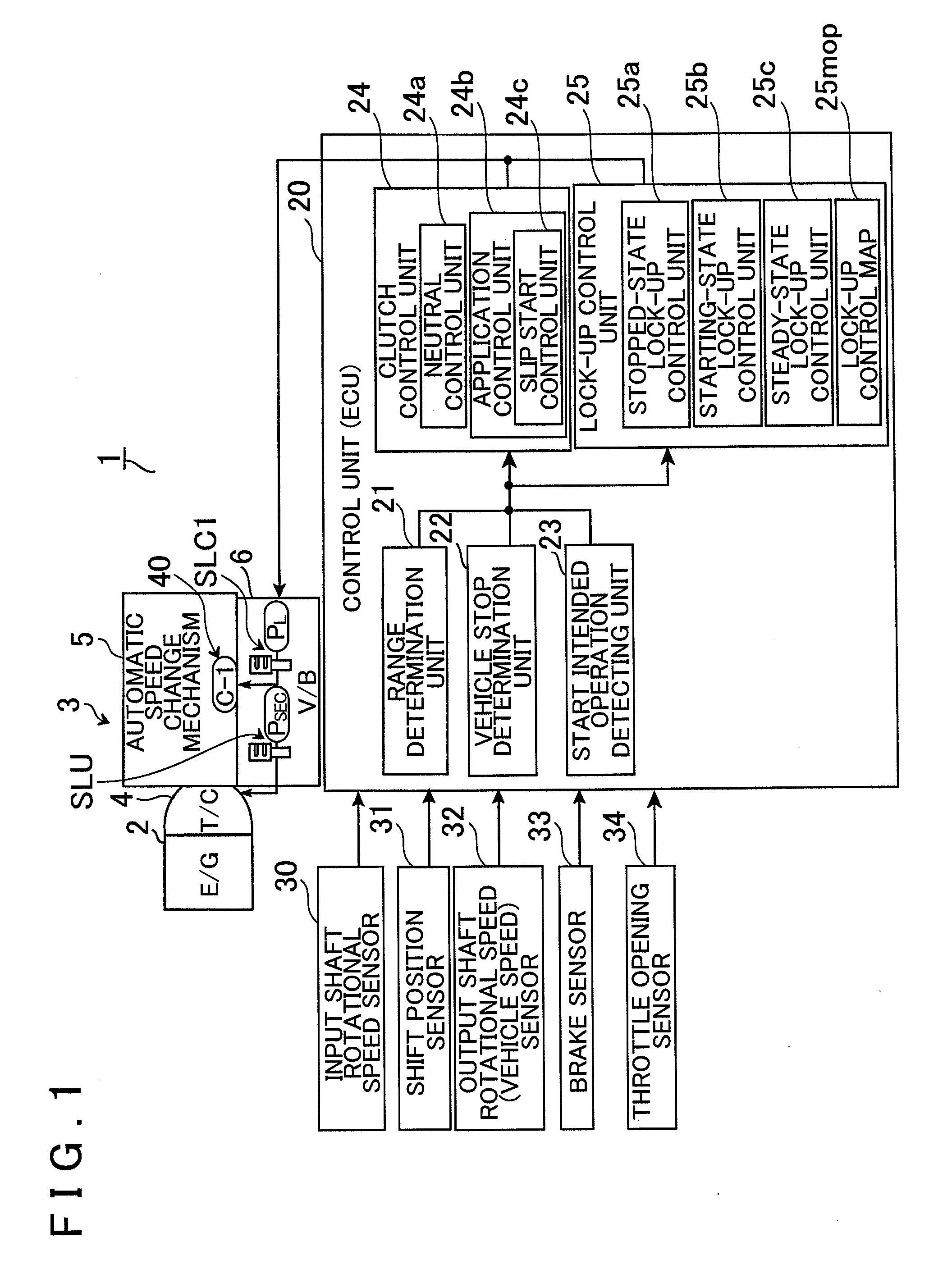
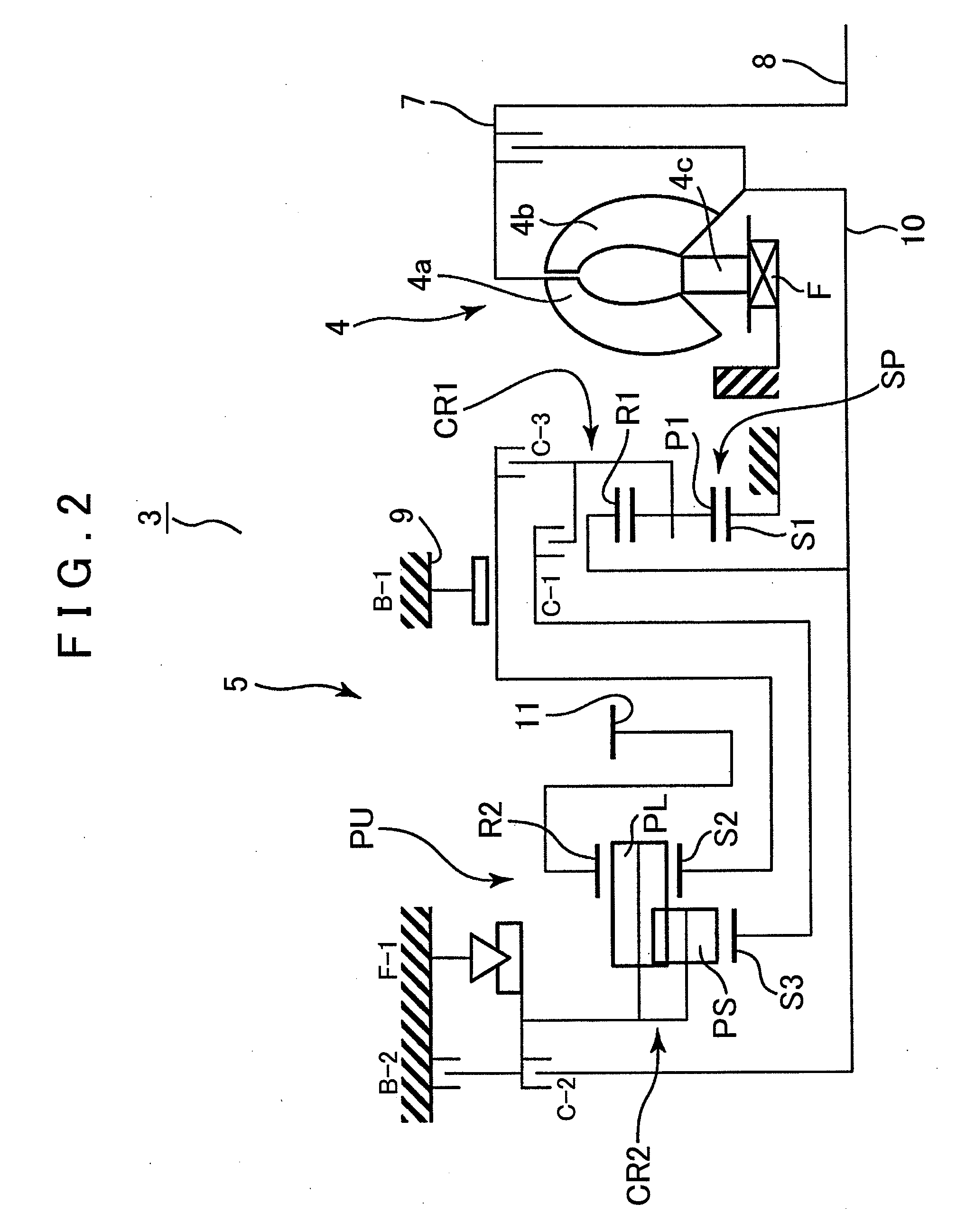
[0032]First of all, an outline structure of an automatic transmission 3 to which the present invention can be applied will be described with reference to FIG. 2. As shown in FIG. 2, the automatic transmission 3 preferably used for a vehicle of an FF type (front engine, front drive), for example, has an input shaft 8 for the automatic transmission that can be connected to an output shaft 2a of an engine (E / G) 2 (refer to FIG. 1) serving as a driving source, and also has a torque converter (fluid transmission apparatus) (T / C) 4 and an automatic speed change mechanism 5 that are disposed about the axial direction of the input shaft 8.

[0033]The torque converter 4 is interposed between the engine 2 and the automatic speed change mechanism 5 to be described in detail later, and has a pump impeller 4a connected to the input shaft 8 of the a...


PUM


Abstract

A control apparatus of an automatic transmission having an automatic speed change mechanism for changing a driving source speed of rotation and a clutch engaged at a start, a fluid transmission apparatus between the driving source and the automatic speed change mechanism, and a lock-up clutch for locking up the fluid transmission apparatus. The control apparatus includes a range unit that determines a shift range including a drive range, a vehicle stop unit that determines a stop of a vehicle, a start intended operation unit that detects an intended start vehicle operation, a clutch control unit that controls the clutch to be disengaged to place the automatic speed change mechanism in a neutral state while the shift range is determined to be the drive range and the vehicle is determined to be stopped, and performs engagement control of the clutch to control the start of the vehicle when the operation intended for starting the vehicle is detected, and a lock-up clutch control unit that controls the lock-up clutch to be engaged while the shift range is determined to be the drive range and the vehicle is determined to be stopped, and controls the lock-up clutch so that the lock-up clutch is at least engaged in a slip region in which a predetermined torque capacity is obtained, when the operation intended for starting the vehicle is detected.

Description

INCORPORATION BY REFERENCE[0001]The disclosure of Japanese Patent Application No. 2010-082527 filed on Mar. 31, 2010 including the specification, drawings and abstract is incorporated herein by reference in its entirety.BACKGROUND OF THE INVENTION[0002]The present invention relates to a control apparatus of an automatic transmission mounted, for example, in a vehicle, and specifically to a control apparatus of an automatic transmission that starts a vehicle while controlling a clutch of an automatic speed change mechanism and a lock-up clutch.DESCRIPTION OF THE RELATED ART[0003]In recent years, a majority of automatic transmissions mounted in vehicles and so on are provided with a torque converter between an engine and an automatic speed change mechanism, and the torque converter is provided with a lock-up clutch. The lock-up clutch is generally locked when a vehicle speed has increased to a predetermined speed or more, thereby reducing a fluid transmission loss of the fluid transmi...

Claims


Application Information

Patent Timeline
Patent Type & Authority Applications(United States)
IPC IPC(8): F16D48/06
CPCF16H61/143F16H2312/022F16H61/686
Inventor TSUTSUI, HIROSHITERAOKA, YUTAKAICHIKAWA, MASATAKEOMITSU, SHOJI
Owner AISIN AW CO LTD
Why Eureka
Try Eureka