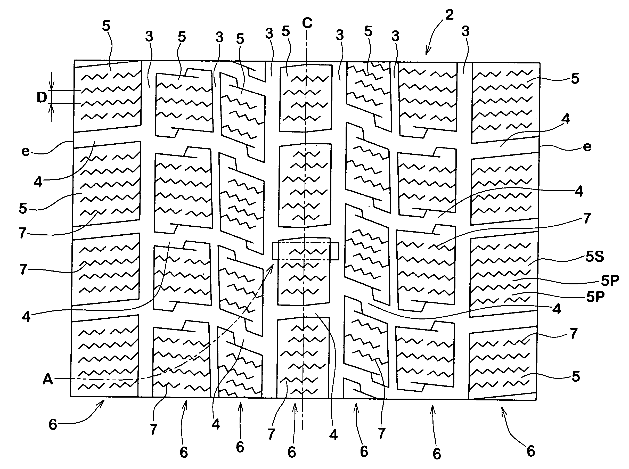
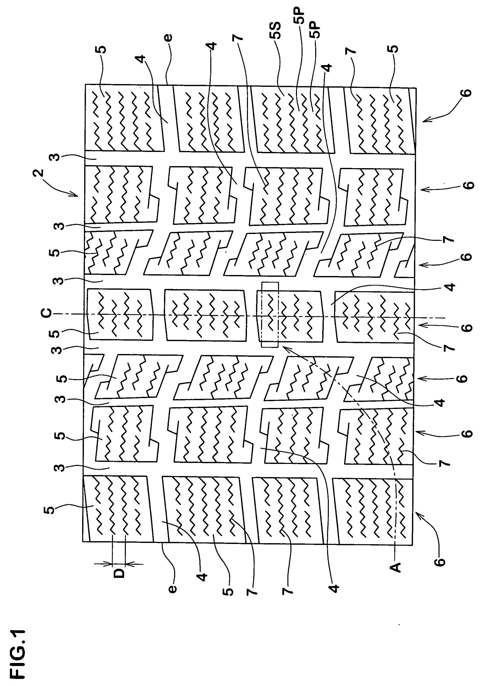
Pneumatic tire

a pneumatic tire and tire mold technology, applied in the field of pneumatic tires, can solve the problems of rubber scraping the blade deformation of the sipe, and the scraping of rubber from the surface of the sipe, so as to reduce the resistance to the removal of the vulcanized tire from the tire mold

Inactive Publication Date: 2005-07-14
SUMITOMO RUBBER IND LTD
View PDF9 Cites 19 Cited by
  • Summary
  • Abstract
  • Description
  • Claims
  • Application Information

AI Technical Summary

Benefits of technology

[0008] It is therefore, an object of the present invention to provide a pneumatic tire with sipes, in which the resistance to removing the vulcanized tire from

Problems solved by technology

In case of a sipe having three-dimensional side walls, however, when the vulcanized tire is removed from a tire mold, as the resistance becomes increased, there is a tendency for the

Method used


Image

  • Pneumatic tire
  • Pneumatic tire
  • Pneumatic tire

Examples


examples

[0053] As shown in FIG. 8A, there is produced a block model in which four sipes (having a common depth 9.0 mm and detailed specification in Table 1) are formed at regular intervals in a rectangular rubber block (width in a tire axial direction: 15 mm, length in a tire circumferential direction: 20 mm, height: 10 mm). Then, various tests are conduced thereto. Testing methods are as follows.

Block Rigidity Test

[0054] As shown in FIG. 8B, the block model is pushed to the flat surface by applying a vertical load P=269 kPa, and a shear force F is applied such that a shear deformation amount δ of the block model becomes 3 mm. The rigidity of the block model is estimated on the basis of the magnitude of the shear force F at this time. Results are expressed by an index obtained by setting the shear force of Comparative Example 1 to 100. The larger the numerical value is, the better the rigidity is.

Knife Blade Drawing Property Test

[0055] The rubber block is vulcanized by using the knife...


PUM

PropertyMeasurementUnit
Angleaaaaaaaaaa
Lengthaaaaaaaaaa

Abstract

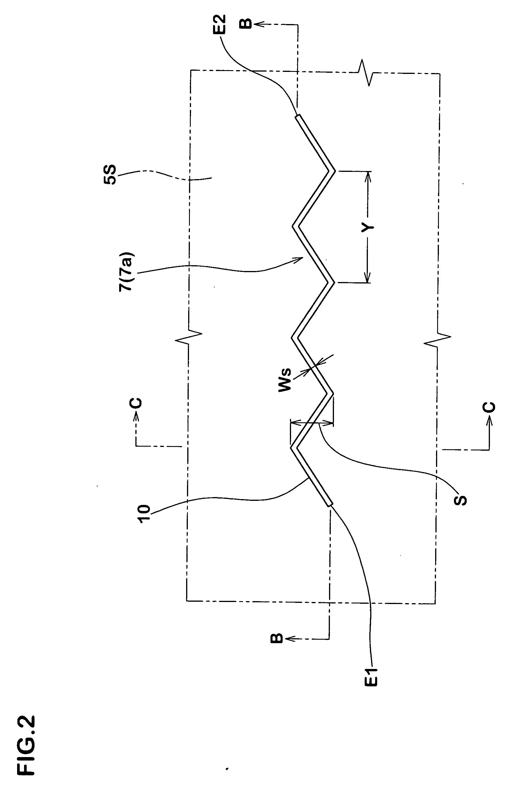
A pneumatic tire comprising a tread portion having tread elements each provided with a sipe, wherein the sipe is open to a upper surface of the tread element, and has an open top end including a zigzag part and a bottom, wherein the sipe comprises: a first portion in which the zigzag part of the open top end extends to a side of the bottom in a state of being inclined to one side of a longitudinal direction of the sipe; a second portion connected to an inner side in a radial direction of the first portion, and in which the zigzag part extends to the side of the bottom in a state of being inclined in an opposite direction to the first portion; and a third portion connected to an inner side in a radial direction of the second portion, and in which the zigzag part extends to the side of the bottom in a state of being inclined in an opposite direction to the second portion, and the sipe satisfies the following relation (1):
α1>α2>α3  (1)
    • [0001]
    • where α1 is a ratio (a1/h1) between a displacement length a1 of the first portion and a length h1 in a radial direction of the first portion, α2 is a ratio (a2/h2) between a displacement length a2 of the second portion direction and a length h2 in a radial direction of the second portion, and α3 is a ratio (a3/h3) between a displacement length a3 of the third portion and a length h3 in a radial direction of the third portion.

Description

BACKGROUND OF THE INVENTION [0002] 1. Field of the Invention [0003] The present invention relates to a pneumatic tire provided in the tread portion with sipes, more particularly to an improved shape of a sipe being capable of preventing the siping blade of a tire vulcanizing mold from bending and coming off therefrom at the time of removing the vulcanized tire from the mold. [0004] 2. Prior Art [0005] In general, pneumatic tires such as snow tire and studless tire called “winter tire” are provided in the tread portion with a number of sipes to improve on-the-ice performance. Such performance may be improved by increasing the number of the sipes and / or the length of the sipes. [0006] In recent years, on the other hand, in order to engage the side walls of a sipe with each other and thereby to give support to each other, the use of a sipe having three-dimensional side walls has been proposed. [0007] In case of a sipe having three-dimensional side walls, however, when the vulcanized ti...

Claims


Application Information

Patent Timeline
IPC IPC(8): B60C11/12
CPCB29D2030/0613B60C2011/1254B60C11/1218B60C11/12Y10S152/03Y10S152/902
Inventor KISHIDA, MASAHIRO
Owner SUMITOMO RUBBER IND LTD
Why Eureka
Try Eureka