
Loop-shaped Sling Adapter for use on Buffer Tube Assembly or Rifle Stock

a buffer tube and adapter technology, applied in the field of slings for weapons, can solve problems such as unfavorable handling, and achieve the effects of convenient, flexible, and inexpensiv

Inactive Publication Date: 2010-11-18
SUPERIOR SHOOTING SYSTEMS INC
View PDF13 Cites 63 Cited by
  • Summary
  • Abstract
  • Description
  • Claims
  • Application Information

AI Technical Summary

Benefits of technology

[0012]Accordingly, it is an object of the present invention to overcome the above mentioned difficulties by providing a convenient, flexible, inexpensive and unobtrusive system and method for allowing users to attach a single point sling to a weapon such as a rifle or carbine.
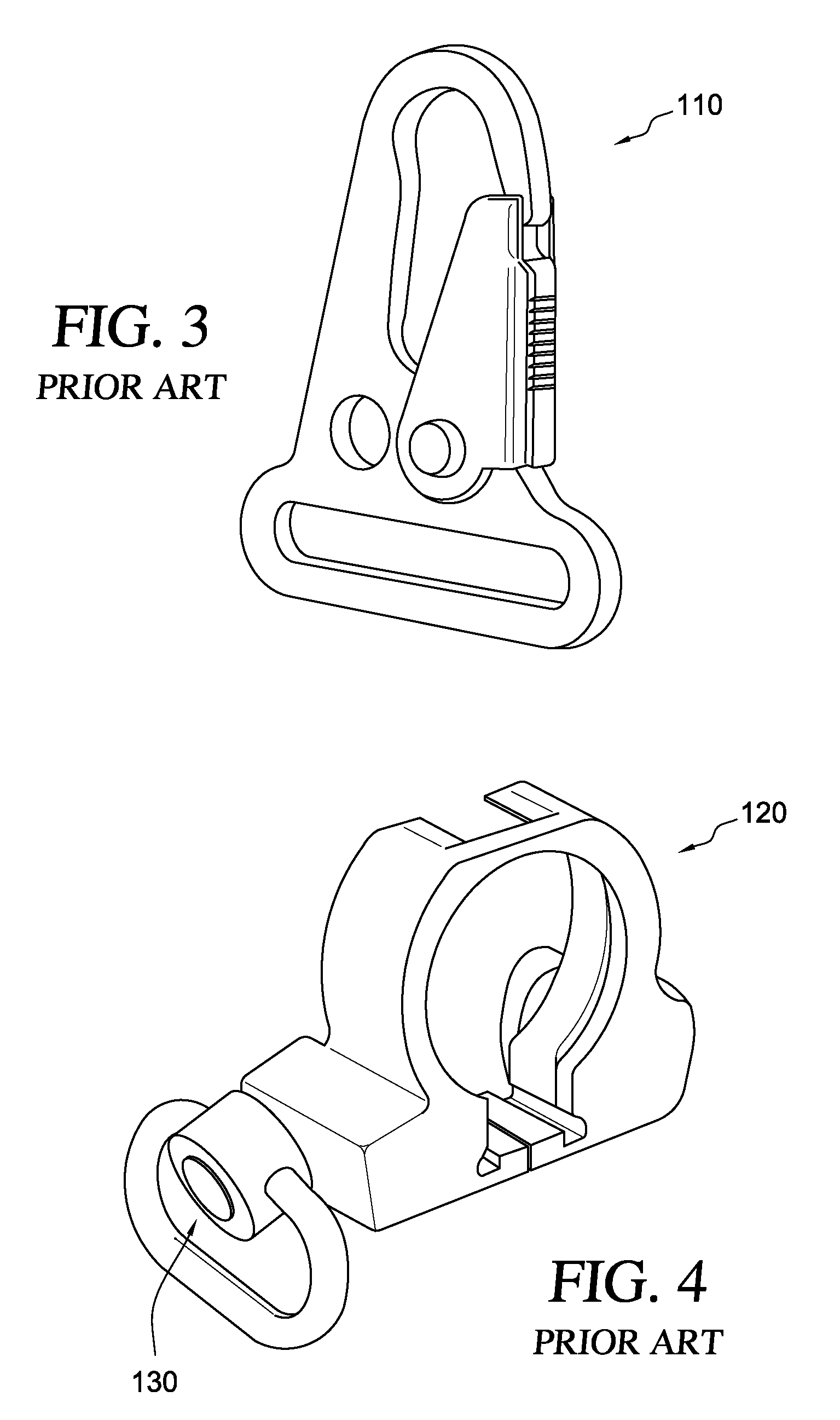
[0014]When compared to the button-actuated sling attachment of FIG. 4, the loop-shaped clamping member of the present invention is more natural, because there is no requirement to execute the pushing and lifting (pulling) movement to release the sling swivel. Instead, the loop-shaped clamping member of the present invention is configured to work well with an HK style hook (with a spring biased safety catch or lever) because the loop-shaped clamping member orients the user's movements in a single direction of movement when releasing a sling. In other words, in a life threatening situation, it is much easier to depress and release a snapped hook from the loop-shaped clamping member than it is to punch the center release button on the quick release swivel while trying to pull away the sling.

Problems solved by technology

As noted above, a vertically slotted sling connection point gives rise to twisted slings, and that makes for awkward handling.

Method used


Image

  • Loop-shaped Sling Adapter for use on Buffer Tube Assembly or Rifle Stock
  • Loop-shaped Sling Adapter for use on Buffer Tube Assembly or Rifle Stock
  • Loop-shaped Sling Adapter for use on Buffer Tube Assembly or Rifle Stock

Examples


Embodiment Construction

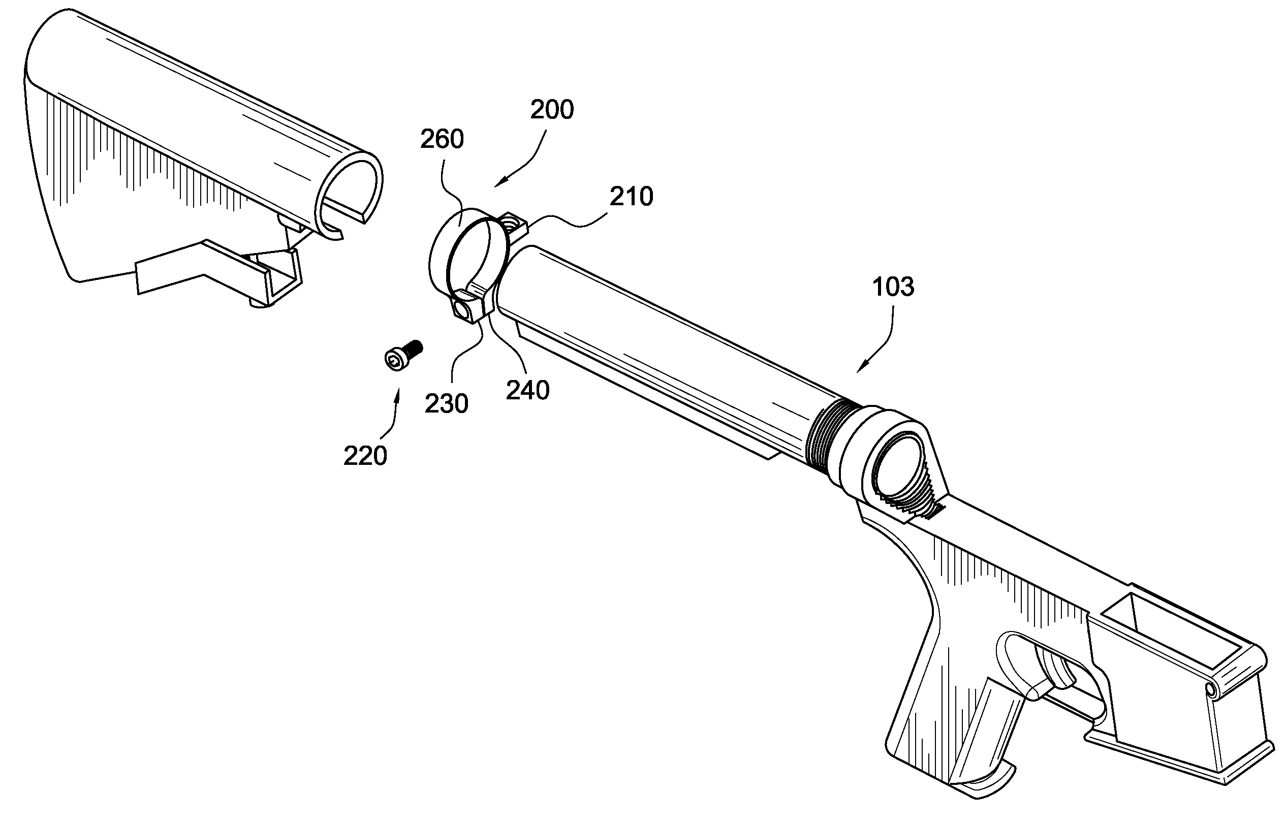
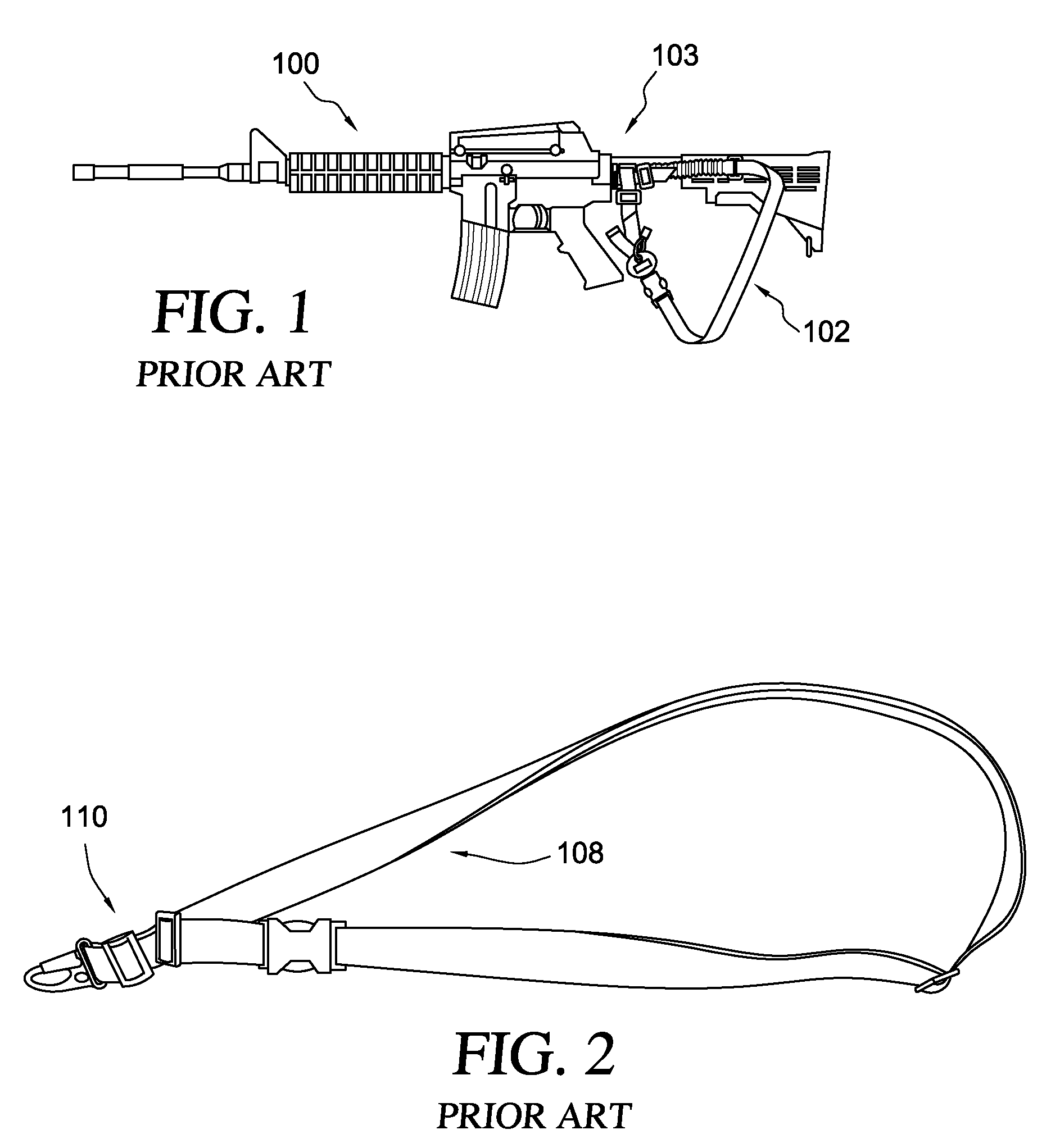
[0051]Turning now to FIGS. 1-9G, a loop-shaped clamping member 200 is illustrated in several views. Loop-shaped clamping member 200 is configured with a transversely projecting boss member 210 which has an aperture 222 therethrough to provide an ideal sling attachment point. A sling such as sling 108 with latching hook 110 as illustrated in FIGS. 2 and 3 is preferred. Boss aperture 222 provides a substantially circular through-bore whose diameter is approximately 0.25″ with chamfered edges at both ends of the through bore, and so provides a snag-free, essentially cylindrical lumen to receive and engage latching hook 110 and to provide a durable and trouble-free sling connection.

[0052]As noted above, vertically slotted sling connection points as used in the prior art give rise to twisted slings and make the rifle (e.g. 100) awkward to handle.

[0053]The loop-shaped clamping member's transversely projecting connection point or boss 210 is horizontal and so allows a single point sling 10...


PUM


Abstract

A clamping sling attachment is configured for use on a carbine or rifle such as the M4 having it's a butt stock mounted on a cylindrical proximally projecting buffer tube, where a distal end of the buffer tube is threaded into the rear of the rifle's receiver. The sling attachment is releasably mountable on the buffer tube as an openable spring-clamp like loop which can be opened enough to go around the buffer tube's cylindrical outer wall. The sling attachment also has a laterally or transversely projecting sling mount defining a substantially vertical, transverse sling-hook receiving through-bore on one side to which the lower end of a weapon sling is releasably attachable. The buffer tube's central axis is the same as the sling attachment loop's central axis and is substantially perpendicular to the sling attachment's transverse sling-hook receiving through-bore.

Description

CROSS-REFERENCE TO RELATED APPLICATIONS AND CLAIM TO PRIORITY[0001]This application claims the benefit of and priority to U.S. provisional patent application No. 61 / 178,966, filed May 16, 2010, the entire disclosure of which is incorporated herein by reference.BACKGROUND OF THE INVENTION[0002]1. Field of the Invention[0003]The present invention relates to slings for weapons and more particularly relates to a sling fitting for a rifle or carbine such as the U.S. M16A2 or M4.[0004]2. Discussion of the Prior Art[0005]Slings are a common accessory used with rifles or carbines such as the M4 (e.g., such as carbine 100, shown in FIG. 1), as well as other types of weapons. The standard AR15 or M16 typically uses a two-point sling, as do most conventional rifles. The “two point” nomenclature refers to a first sling connection near the front of the rifle and a second connection near the rear of the rifle.[0006]A sling must either attach to an existing part of the weapon or the weapon must be...

Claims


Application Information

Patent Timeline
IPC IPC(8): F41C23/02
CPCF41C23/02
Inventor KING, JOHNATHAN
Owner SUPERIOR SHOOTING SYSTEMS INC
Learn More