
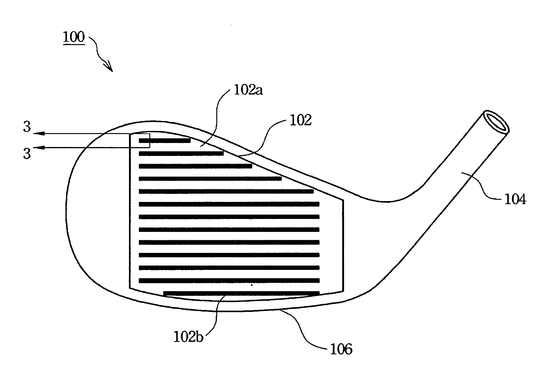
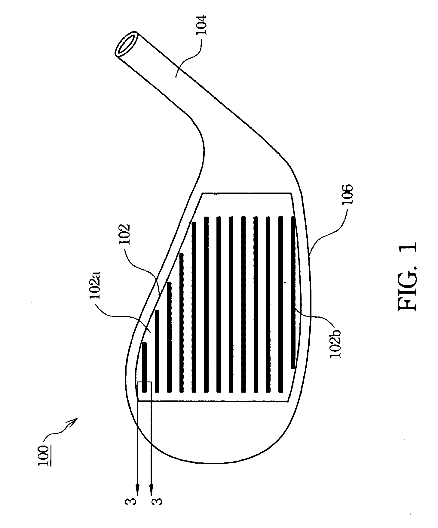
Golf club head

a golf club and club head technology, applied in the field of golf club heads, can solve the problems of difficult to meet the requirements of effective grooves, golf balls to be rolled off the green or in a direction away from the golf hole, and affect the travel distance of golf balls, so as to increase the backspin of golf balls struck, increase the score and competitiveness of golfers in competitions, and increase the bottom width

Inactive Publication Date: 2010-11-18
FUSHENG PRECISION
View PDF11 Cites 0 Cited by
  • Summary
  • Abstract
  • Description
  • Claims
  • Application Information

AI Technical Summary

Benefits of technology

[0010]One advantage of the present invention is to increase the backspin of a golf ball struck by a golfer in order to raise the scores and competitiveness of the golfer in competitions. Furthermore, another advantage of the present invention is that the grooves of the present invention can be designed to have a larger bottom width than conventional V-shaped or U-shaped grooves when the top width thereof is kept the same Therefore, it is relatively easy to machine the grooves of the present invention with less wear on the cutter.
is to increase the backspin of a golf ball struck by a golfer in order to raise the scores and competitiveness of the golfer in competitions. Furthermore, another advantage of the present invention is that the grooves of the present invention can be designed to have a larger bottom width than conventional V-shaped or U-shaped grooves when the top width thereof is kept the same Therefore, it is relatively easy to machine the grooves of the present invention with less wear on the cutter.

Problems solved by technology

However, during competitions, the ball's travel distance is not only affected by the selected the golf club but also by what happens after the ball strikes the ground.
Conversely, lack of sufficient backspin will create too much forward roll after landing on the ground, which can cause a golf ball to unmanageably roll either off of the green or in a direction away from a golf hole.
Under the USGA rules, it is very difficult to fulfill the requirements of effective grooves that impart enough backspin to the struck ball.
Grooves capable of providing a relatively large amount of backspin usually can't meet the USGA rules.

Method used


Image

  • Golf club head
  • Golf club head
  • Golf club head

Examples


embodiment

Manufacturing Golf Club Head Including Striking Plate Having Grooves with Involute Profile

[0032]First, the main body and the striking plate of a golf club head are cast, wherein the main body includes a toe portion, a sole portion, a top portion and a heel portion. Hereafter, a plurality of grooves are manufactured on the striking face of the striking plate by machining tools such that the cross section shape of each groove is identical with that shown in FIG. 5A. Alternatively, the grooves also can be manufactured by casting. In FIG. 5A, the angles θ3 of different golf club heads are respectively 28.5 degrees, 35 degrees, and 40 degrees. The lines 502 are respectively drawn tangent to the involute profiles of the golf club heads' striking plates at a top end-point thereof, wherein the top end-point is located on the striking face of a striking plate, and the bottom surface of each golf club head's grooves has a normal line 504 perpendicular thereto. θ3 represents the angle included...


PUM


Abstract

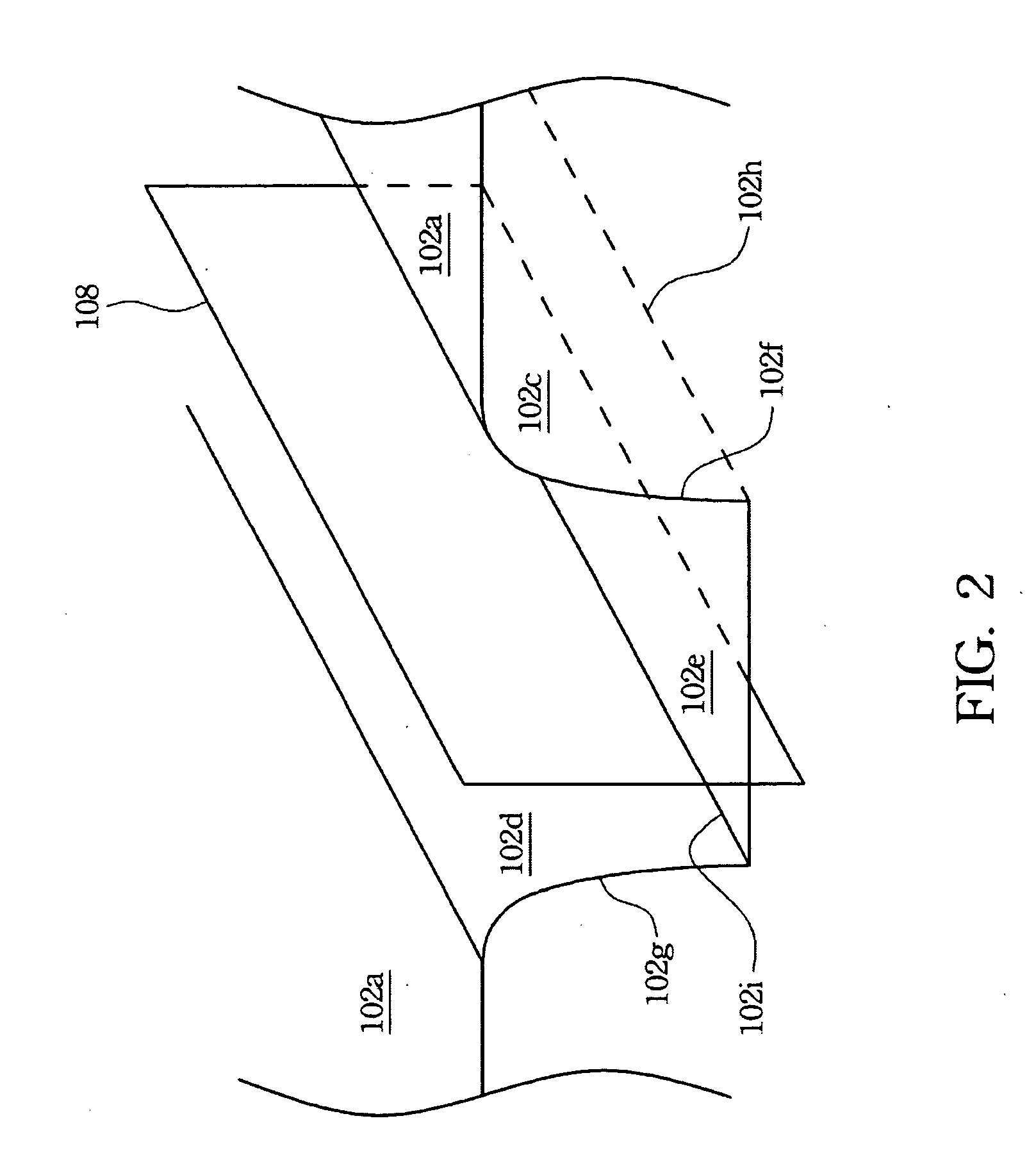
A golf club head includes a striking face having a plurality of grooves formed therein. At least one groove includes a first curved side surface, a second curved side surface opposite to the first curved side surface, and a bottom surface connecting the first and the second curved side surfaces. As viewed in the longitudinal direction of the at least one groove, the first and the second curved surfaces respectively have first and second involute profiles. A distance measured between the first and the second curved surfaces continuously increases from the bottom surface to the striking face.

Description

BACKGROUND[0001]1. Field of Invention[0002]The present invention relates to a golf club head, and more particularly to a golf club head including at least one groove disposed on a striking face of the golf club head and having a specific profile.[0003]2. Description of Related Art[0004]During competitions, golfers generally select a particular golf club according to how far it is desired for a golf ball to travel after the golf ball is struck by the club. However, during competitions, the ball's travel distance is not only affected by the selected the golf club but also by what happens after the ball strikes the ground. After the ball strikes the ground, its movement is primarily affected by the amount of backspin imparted on the ball by the golf club. A ball having a greater amount of backspin after being struck will have less forward roll after it lands on the ground. In general, less forward roll provides precision landing of the golf ball on a golf green. Conversely, lack of suf...

Claims


Application Information

Patent Timeline
Patent Type & Authority Applications(United States)
IPC IPC(8): A63B53/04
CPCA63B53/047A63B2053/0408A63B2209/00A63B2053/0445A63B53/0445A63B53/0408
Inventor CHEN, CHAN-TUNGHOU, WEN-CHINGLIN, CHIANG-TAICHUANG, JIUN-HSENGWU, CHUN-HAN
Owner FUSHENG PRECISION
Learn More