Signal testing system and method of a printed circuit board

a technology of printed circuit boards and signal testing systems, applied in the field of circuit testing, can solve the problems of difficult to reach the test points of electronic signals in the pcbs, inconvenient manual testing, time-consuming,

Inactive Publication Date: 2010-11-25
HON HAI PRECISION IND CO LTD
View PDF6 Cites 23 Cited by
  • Summary
  • Abstract
  • Description
  • Claims
  • Application Information

AI Technical Summary

Benefits of technology

[0002]Embodiments of the present disclosure relate to circuit testing, and particularly to a signal testing system and method of a printed circuit board.

Problems solved by technology

Because the signal testing of the PCBs involves numerous electronic signals, the manual testing can be very inconvenient and time consuming.
Additionally, test points of the electronic signals in the PCBs are sometimes difficult to reach due to increasing complexity of the PCBs.

Method used


Image

  • Signal testing system and method of a printed circuit board
  • Signal testing system and method of a printed circuit board
  • Signal testing system and method of a printed circuit board

Examples


Embodiment Construction

[0008]All of the processes described below may be embodied in, and fully automated via, functional code modules executed by one or more general purpose computers or processors. The code modules may be stored in any type of computer-readable medium or other computer storage device. Some or all of the methods may alternatively be embodied in specialized computer hardware.

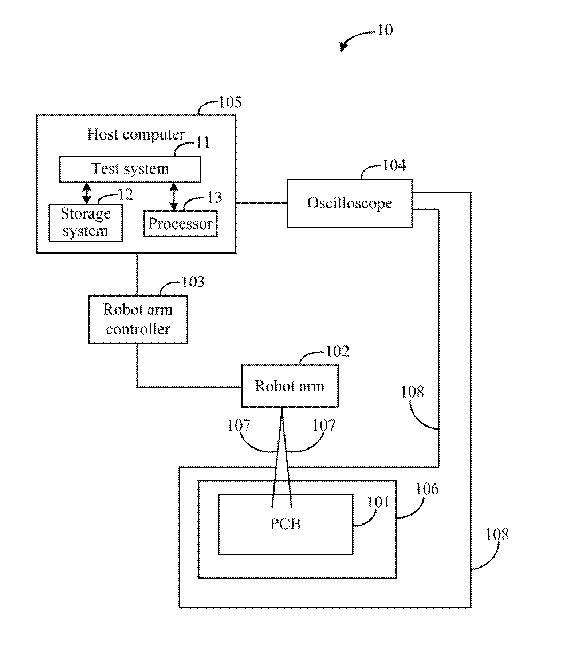
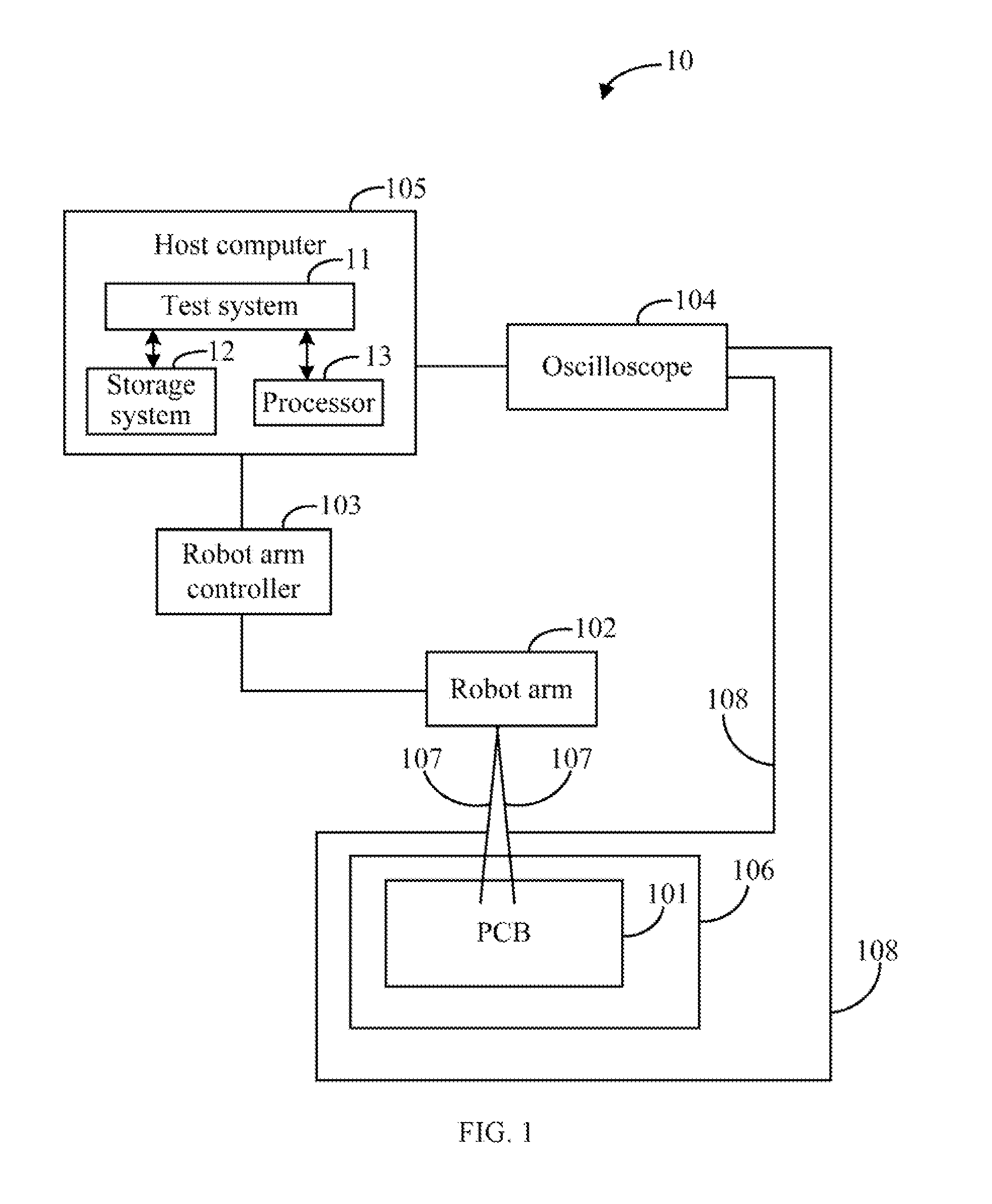
[0009]FIG. 1 is a block diagram of one embodiment of a signal testing system 10 of a printed circuit board (PCB) 101. The PCB 101 (e.g., a motherboard) may include a bare board and various electronic components, such as resistors, capacitors, and integrated circuits. In one embodiment, the signal testing system 10 includes a robot arm 102, a robot arm controller 103, an oscilloscope 104, and a host computer 105. The PCB 101 may be placed on a test rack 106. The host computer 105 is connected to the robot arm controller 103 and the oscilloscope 104 via input / output (I / O) interfaces, such as serial ports, general purpos...


PUM


Abstract

A signal testing method of a printed circuit board (PCB) applies a robot arm and an oscilloscope to test the PCB. The method controls the robot arm to move to test points of electronic signals of the PCB. The method further controls the oscilloscope connected to the robot arm to measure the electronic signals.

Description

BACKGROUND[0001]1. Technical Field[0002]Embodiments of the present disclosure relate to circuit testing, and particularly to a signal testing system and method of a printed circuit board.[0003]2. Description of Related Art[0004]Signal testing of a printed circuit board (PCB), such as a motherboard, is an important phase in the manufacturing process and is closely interrelated to product quality. Currently, the signal testing of PCBs is manually operated using an oscilloscope. Because the signal testing of the PCBs involves numerous electronic signals, the manual testing can be very inconvenient and time consuming. Additionally, test points of the electronic signals in the PCBs are sometimes difficult to reach due to increasing complexity of the PCBs. A robot arm can be controlled to move to specified locations accurately and efficiently. Therefore, prompt and accurate signal test of the printed circuit board using the robot arm is desirable.BRIEF DESCRIPTION OF THE DRAWINGS[0005]FIG...

Claims


Application Information

Patent Timeline
Patent Type & Authority Applications(United States)
IPC IPC(8): G01R31/02
CPCG01R31/2808
Inventor LI, SHEN-CHUNHSU, SHOU-KUO
Owner HON HAI PRECISION IND CO LTD
Why Eureka
Try Eureka