Electronic device with sensing assembly and method for interpreting offset gestures

a sensing assembly and electronic device technology, applied in the field of electronic devices, can solve the problems of limited touch screen, limited sensing devices in various respects, and complicated electronic devices that are expensive on the touch screen

Inactive Publication Date: 2010-11-25
GOOGLE TECH HLDG LLC
View PDF99 Cites 141 Cited by
  • Summary
  • Abstract
  • Description
  • Claims
  • Application Information

AI Technical Summary

Problems solved by technology

Although prior art devices such as capacitive touch screens are useful as input/output devices for phones, such touch screens are fairly complicated electronic devices that are expensive and require a large number of sensing devices that are distributed in location across a large surface area of the phone.
Also, such touch screens are limited insofar as they only allow a user to provide input signals if the user is actually physically touching the touch screens.
Further, while remote sensing devices such as infrared (or, more accurately, near-infrared) transceivers have been employed in the past in some mobile devices to allow for the detection of the presence and/or location of human beings and/or physical objects even when not in physical contact with

Method used


Image

  • Electronic device with sensing assembly and method for interpreting offset gestures
  • Electronic device with sensing assembly and method for interpreting offset gestures
  • Electronic device with sensing assembly and method for interpreting offset gestures

Examples


Embodiment Construction

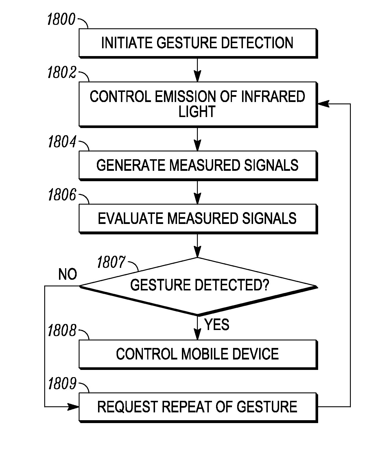
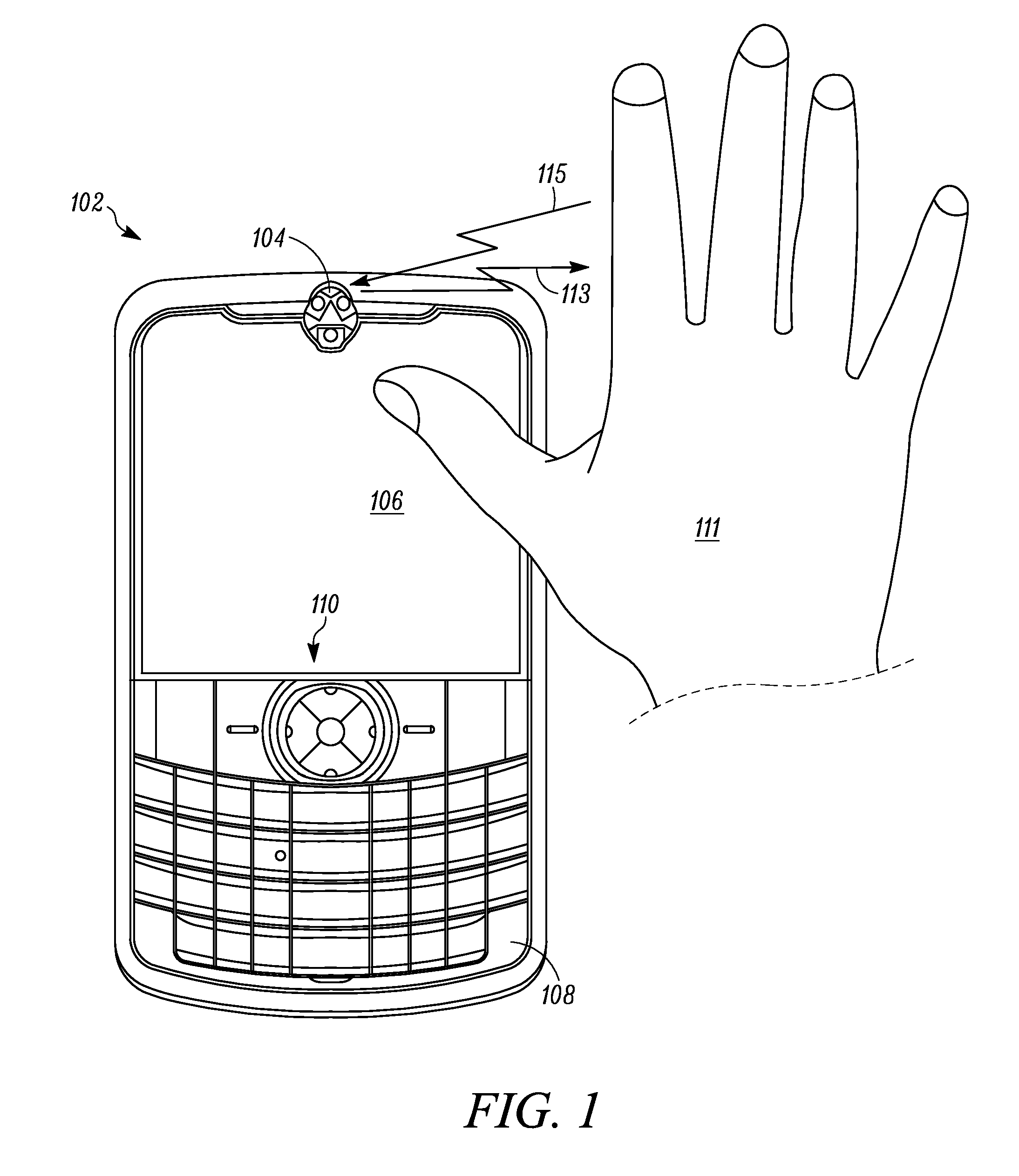
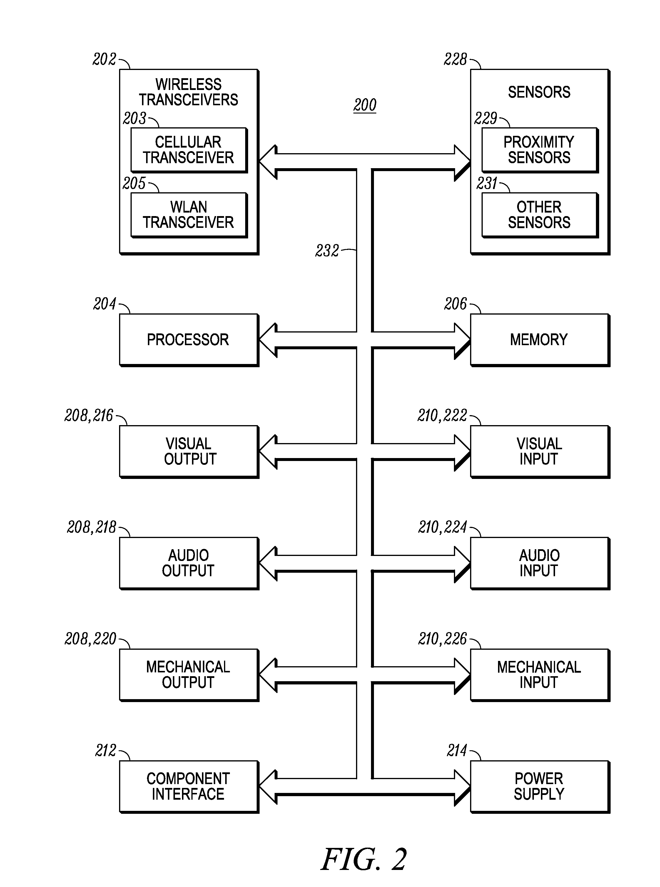
[0032]An infrared sensing assembly enables detection of one or more gestures, where the gestures are predetermined patterns of movement of an external object relative to an electronic device that also includes a processor in communication with the sensing assembly. These gestures can be defined to be performed in a three dimensional space and can include for example, a push / pull gesture (movement of the object toward or away from the electronic device along a z axis), a slide gesture (movement of the object in an xy plane across the electronic device), a hover gesture (stationary placement of the object for a predetermined amount of time), and a tilt gesture (rotation of the object about a roll, pitch, or yaw axis). Detection of these gestures can be used to control the electronic device in a variety of ways. The infrared sensing assembly can be configured in various forms and includes one or more phototransmitters which are controlled to emit infrared light outward away from the el...


PUM


Abstract

A method for controlling an electronic device includes providing as part of the electronic device a display screen for displaying content and a sensing assembly including at least one photoreceiver and a plurality of phototransmitters, wherein each phototransmitter is positioned to emit infrared light away from the electronic device about a corresponding central transmission axis, wherein each central transmission axis is oriented in a different direction with respect to the others. Emission of infrared light by each of the phototransmitters is controlled during each of a plurality of time periods as an external object moves in a first specified pattern of movement and then moves in a second specified pattern of movement which is offset from a generally centered position with respect to the sensing assembly, and measured signals are generated. The measured signals are evaluated to identify the first specified pattern of movement of the object, to detect a reference offset location corresponding to an end of the first specified pattern of movement of the object, and to determine, for each of a group of time periods when the object is moving in the second specified pattern of movement, a corresponding location of the object during that time period. A centering operation is performed in response to the identification of the first specified pattern of movement, wherein the centering operation moves an indicator to an initial predetermined reference location on the display screen, wherein the predetermined reference location is then associated with the reference offset location; and sequential locations of the indicator on the display screen are controlled in accordance with the corresponding determined locations of the object relative to the reference offset location.

Description

CROSS-REFERENCE TO RELATED APPLICATIONS[0001]This application is a continuation-in-part of and claims the benefit of U.S. patent application Ser. No. 12 / 471,062, titled “Sensing Assembly For Mobile Device” and filed on May 22, 2009, which is hereby incorporated by reference herein.STATEMENT REGARDING FEDERALLY SPONSORED RESEARCH OR DEVELOPMENTFIELD OF THE INVENTION[0002]The present invention relates generally to electronic devices and, more particularly, to an electronic device having an infrared sensing assembly for detecting and interpreting gestures which are performed by an object that is offset from the sensing assembly and / or a display screen of the electronic device.BACKGROUND OF THE INVENTION[0003]Mobile devices such as cellular telephones, smart phones, and other handheld or portable electronic devices such as personal digital assistants (PDAs), headsets, MP3 players, etc. have become popular and ubiquitous. As more and more features have been added to mobile devices, there...

Claims


Application Information

Patent Timeline
IPC IPC(8): G06F3/033G09G5/00
CPCH03K17/9631H04W4/023G06F3/0304G06F1/1686G06F3/017H04W4/206H04W4/21G06F3/0346
Inventor ALAMEH, RACHIDMERRELL, THOMASPAITL, KENNETH A.
Owner GOOGLE TECH HLDG LLC
Why Eureka
Try Eureka