Optical touch panel

a touch panel and optical technology, applied in the field of optical touch panels, can solve the problems of reducing the clarity of the underlying display, being prone to wear and damage, and capacitive touch panels, and not working when contacted by non-conductive objects

Inactive Publication Date: 2010-11-25
EMINENT ELECTRONICS TECH
View PDF24 Cites 206 Cited by
  • Summary
  • Abstract
  • Description
  • Claims
  • Application Information

AI Technical Summary

Problems solved by technology

While suitable for many applications, resistive type touch panels have their drawbacks, including reducing the clarity of the underlying display and being prone to wear and damage.
Capacitive touch panels are generally intended for use only with an exposed finger of a user and may not work when contacted by non-conductive objects, such as a gloved finger.
Further, capacitive touch panels can become quite expensive as the size of the touch panel is increased.
However, prior optical touch panel designs also suffer from some drawbacks, including low sensing resolution, high power consumption, relatively high costs compared to other touch panel technologies, and inconsistent performance in high ambient light and / or optically noisy environments.

Method used


Image

  • Optical touch panel
  • Optical touch panel
  • Optical touch panel

Examples


Embodiment Construction

[0031]Various embodiments and examples of optical sensors and optical touch panel assemblies are disclosed herein that incorporate aspects of different photosensor designs, arrangements / mechanical mountings for optical components, and programming to determine locations of one or more objects on the touch panel and to interpret the movement of such objects as input gestures, e.g., a slide, pinch, flick, etc. The features of each embodiment are generally interchangeable and can be used in the alternative or in combination with features discussed in relation to other embodiments. Elements that are common to the various embodiments are identified by like reference numerals.

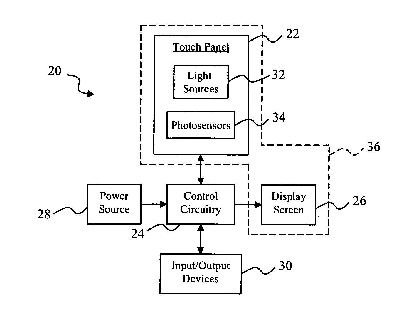
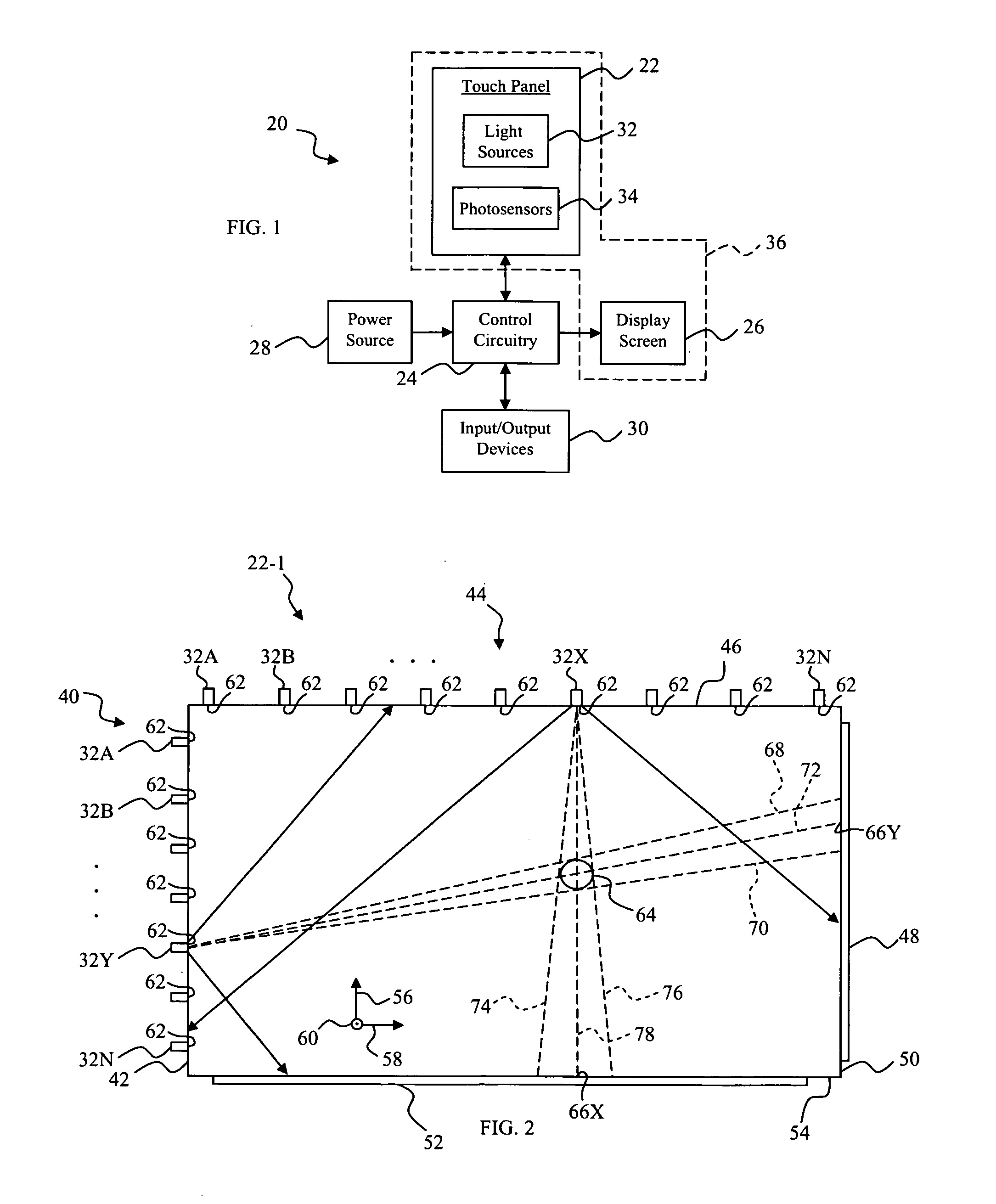
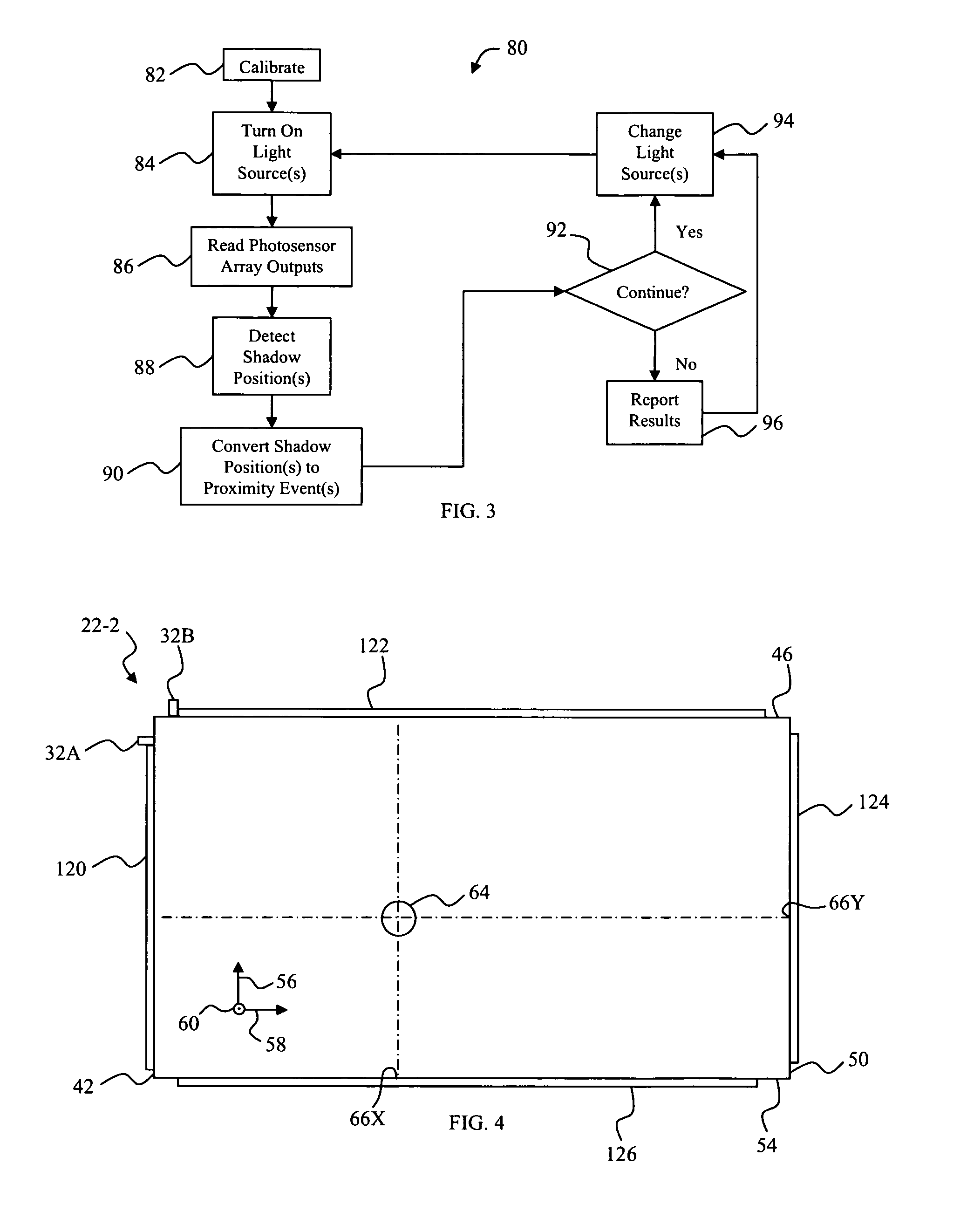
[0032]In one example, a touch panel operates emitters and / or receivers in a multiplexed sequence preferably with one or more emitters and / or receivers operated at a time to determine characteristics of one or more simultaneous proximity events. The emitters and receivers may be light sources and photosensors, respecti...


PUM


Abstract

An optical touch panel assembly includes a touch panel that has photosensors and light sources, wherein each light source is energizable to produce a field of illumination that illuminates multiple photosensors at a time. The touch panel also includes control circuitry to energize and de-energize the light sources so that at least one but less than all of the light sources are turned on at a time in a sequence to illuminate an entire active area of the touch panel and to analyze output signals from the photosensors. The control circuitry is further configured to identify a low level output signal corresponding to a proximity event and to determine a location of the proximity event on the touch panel.

Description

CROSS REFERENCE TO RELATED APPLICATIONS[0001]This application claims the benefit of U.S. Provisional Patent Application No. 61 / 216,656 filed May 20, 2009, which is incorporated by reference herein in its entirety.REFERENCE REGARDING FEDERALLY SPONSORED RESEARCH OR DEVELOPMENT[0002]Not applicableSEQUENTIAL LISTING[0003]Not applicableBACKGROUND OF THE INVENTION[0004]1. Field of the Disclosure[0005]The present disclosure relates to touch panels and, more particularly, to optical touch panels.[0006]2. Background of the Disclosure[0007]Touch panels disposed over or otherwise integrated with display screens, such as, an LCD panel or CRT screen, are becoming increasingly prevalent in smart phones, PDA's, notebook PC's, GPS devices, handheld or personal game consoles, ATM's, kiosks in general, and the like, to serve as an input device that allows a user to interact with a display. An input can generally be entered on the touch panel by any suitable means, e.g., one or more fingers, a palm, ...

Claims


Application Information

Patent Timeline
Patent Type & Authority Applications(United States)
IPC IPC(8): G06F3/042
CPCG06F3/0421G06F2203/04109G06F3/0428
Inventor CHANG, TOMGRZEGOREK, ANDREWZHANG, CHONGMEICANFIELD, JOHN
Owner EMINENT ELECTRONICS TECH
Why Eureka
Try Eureka