High gain miniature power supply for plasma generation

a plasma generator and high gain technology, applied in piezoelectric/electrostrictive/magnetostrictive devices, piezoelectric/electrostriction/magnetostriction machines, electrical equipment, etc., can solve the problems of inability to meet the needs of plasma generators

Inactive Publication Date: 2010-12-02
LOCKHEED MARTIN CORP
View PDF14 Cites 17 Cited by
  • Summary
  • Abstract
  • Description
  • Claims
  • Application Information

AI Technical Summary

Benefits of technology

[0009]a solid-state resonant inverter configured to drive the piezoelectric transformer at a desired piezoelectric transforme

Problems solved by technology

High voltage gain with high power density and low profile dimensions required by certain plasma assisted applications poses challenges for conventional power supply designs.
Such power supply designs are expensive to produce and suffer in reliability due to internal heat build-up during high pulse repetition rate generation.
These conventional power supply designs also undesirably

Method used


Image

  • High gain miniature power supply for plasma generation
  • High gain miniature power supply for plasma generation
  • High gain miniature power supply for plasma generation

Examples


Embodiment Construction

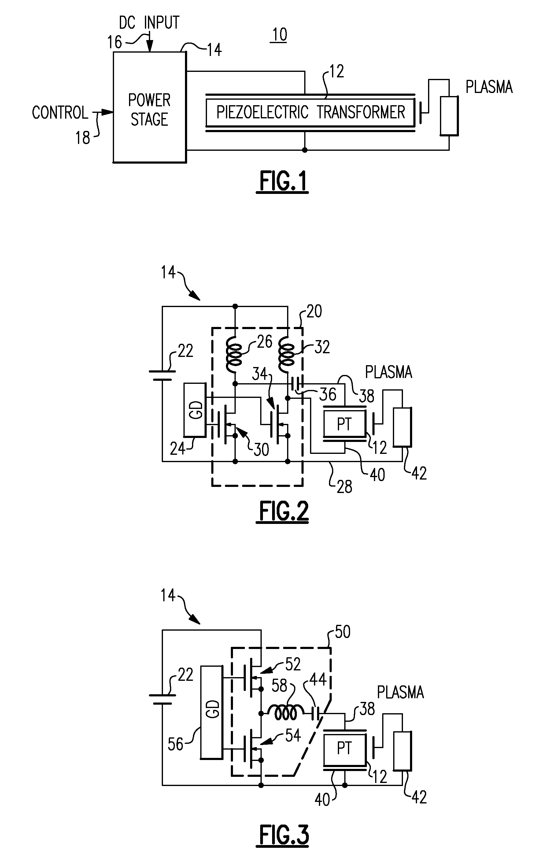
[0020]Plasma actuators for flow control, plasma assisted combustion, and pulse detonation engines, among others, are all applications that may benefit from a plasma generator that achieves a high voltage gain with the advantages of compact size, light weight, high efficiency, less electromagnetic noise, non-flammability, and design flexibility that is not achievable using conventional electromagnetic transformers to achieve a high voltage gain.

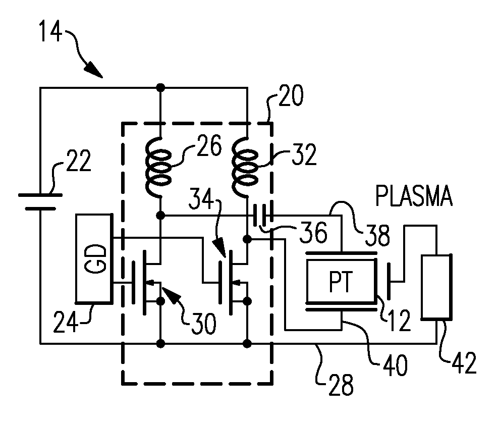
[0021]FIG. 1 is a simplified system block diagram illustrating a high gain plasma generator 10, according to one embodiment of the invention. Plasma generator 10 includes a piezoelectric transformer 12 that is driven via a transformer input power stage 14. According to one aspect of the invention, power input stage 14 includes a DC input 16 and a control input 18. The DC input 16 may be, for example, provided by a battery such as depicted in FIGS. 2-4; while the control input 18, may be, for example, provided by an inverter such as depicted in...


PUM


Abstract

A high gain pulse generator includes a piezoelectric transformer (PT) that is driven by an input power stage to drive the PT at a desired PT resonant frequency such that at least one PT characteristic substantially matches at least one non-linear load characteristic such as, without limitation, a plasma load characteristic to deliver a desired pulse to the non-linear load.

Description

BACKGROUND[0001]The invention relates generally to plasma generators and more particularly to a high gain miniature plasma generator power supply for use in plasma actuators for flow control, plasma assisted combustion and pulse detonation engines.[0002]High voltage gain with high power density and low profile dimensions required by certain plasma assisted applications poses challenges for conventional power supply designs. Conventional power supply designs generally employ electromagnetic transformers for achieving a high voltage gain. Such power supply designs are expensive to produce and suffer in reliability due to internal heat build-up during high pulse repetition rate generation. These conventional power supply designs also undesirably require significant real estate, generally have low electric efficiency, and often introduce unwanted electromagnetic noise. Further, conventional electromagnetic transformer technology is not particularly suitable for many applications requiri...

Claims


Application Information

Patent Timeline
IPC IPC(8): H01L41/107
CPCH01L41/044H10N30/804
Inventor TAO, FENGFENGBENNETT, JR., GROVER ANDREWMUELLER, FRANK JAKOB JOHNMURRAY, ROBERT CARLSADDOUGHI, SEYED GHOLAMALIALLEN, EDWARD HENRY
Owner LOCKHEED MARTIN CORP
Why Eureka
Try Eureka