Expansion joint and method

Inactive Publication Date: 2010-12-09
ZIELONKA KRZYSZTOF
View PDF10 Cites 9 Cited by
  • Summary
  • Abstract
  • Description
  • Claims
  • Application Information

AI Technical Summary

Benefits of technology

[0009]In another aspect of the invention there is an expansion joint. It has an elongated flat sheet of flexible and resilient polymeric material having a width, opposite upper and lower surfaces, and opposite first and second edges. One of the opposite surfaces is a first surface, and has a fibrous section including a section of the sheet having a plurality of fibers secured to the surface. The fibrous section extends along the first surface adjacent one of the edges. A series of apertures passes through the sheet and is positioned on the fibrous section, with the apertures being positioned adjacent one of the side edges.
[0010]In a feature of that aspect of the invention, each of the upper and lower surfaces have the fibrous section. In another feature each of the fibrous sections comprises a parallel pair of first and second fibrous matts secured to the surface. The fibrous matts are separated by an elongated strip of bare surface. The first and second fibrous matts are located adjacent to the first and second edges of the sheet, respectively, with the

Problems solved by technology

Rubber expansion joints may be present some challenges or disadvantages.
For example, on hot summer days, the tar or adhesive used to bond the joint to the underlying substrate and to hold the joint in place may soften or weaken.
This may result in the joint to becoming dislodged and slipping or creeping or migrating away from its desired position.
That is, when the bond holding the joint softens, the joint may tend to move, or cr

Method used


Image

  • Expansion joint and method
  • Expansion joint and method
  • Expansion joint and method

Examples


Embodiment Construction

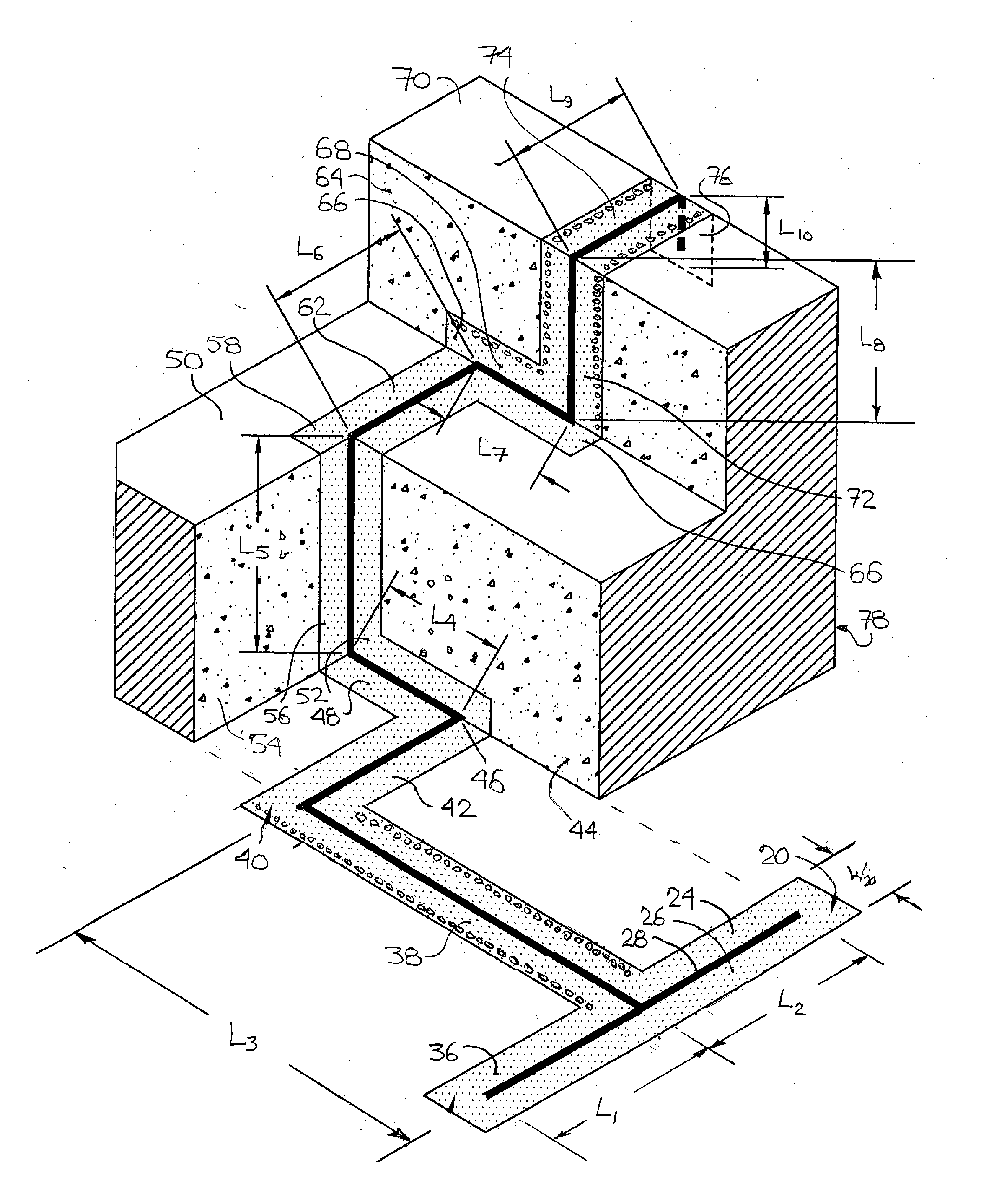
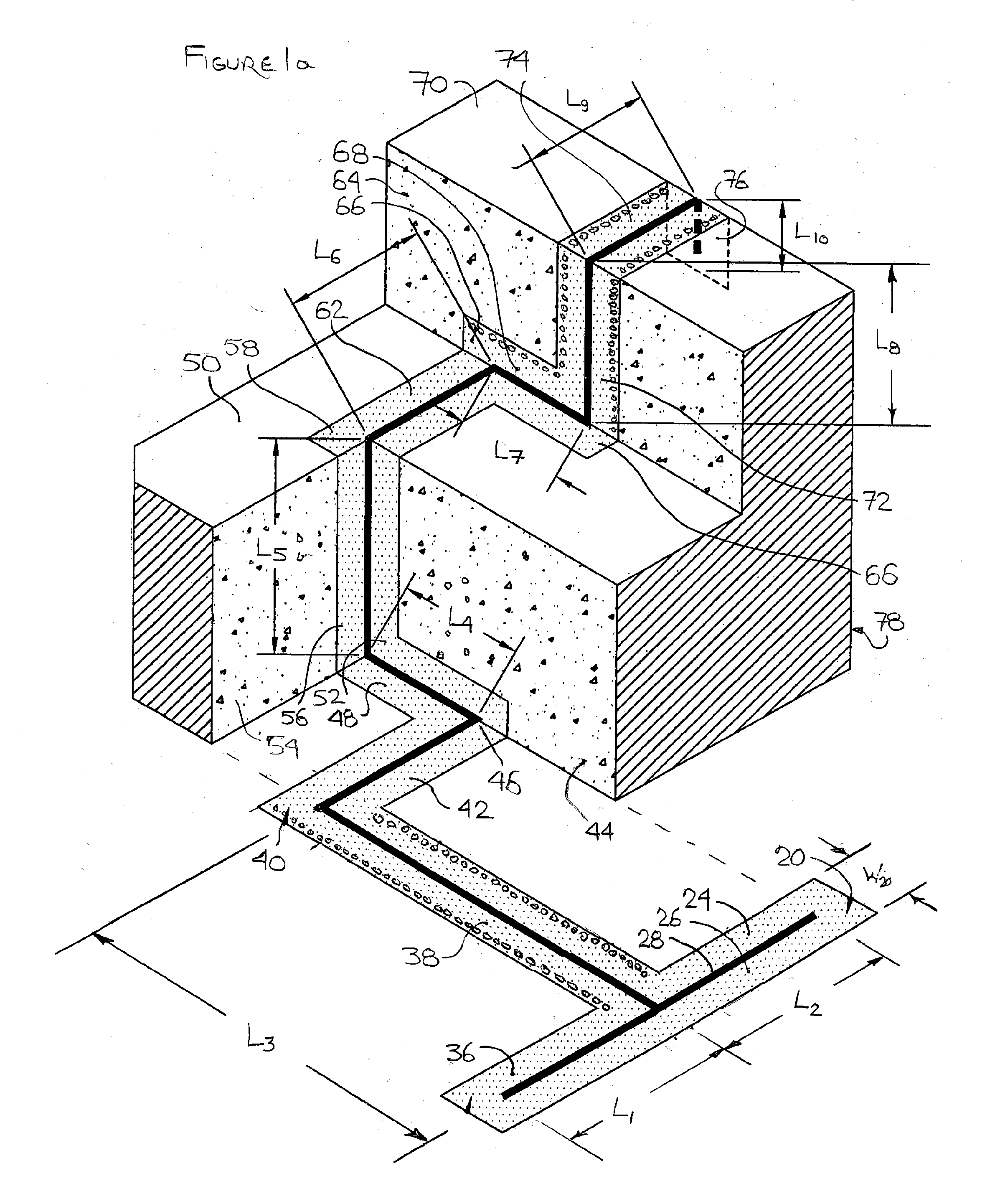
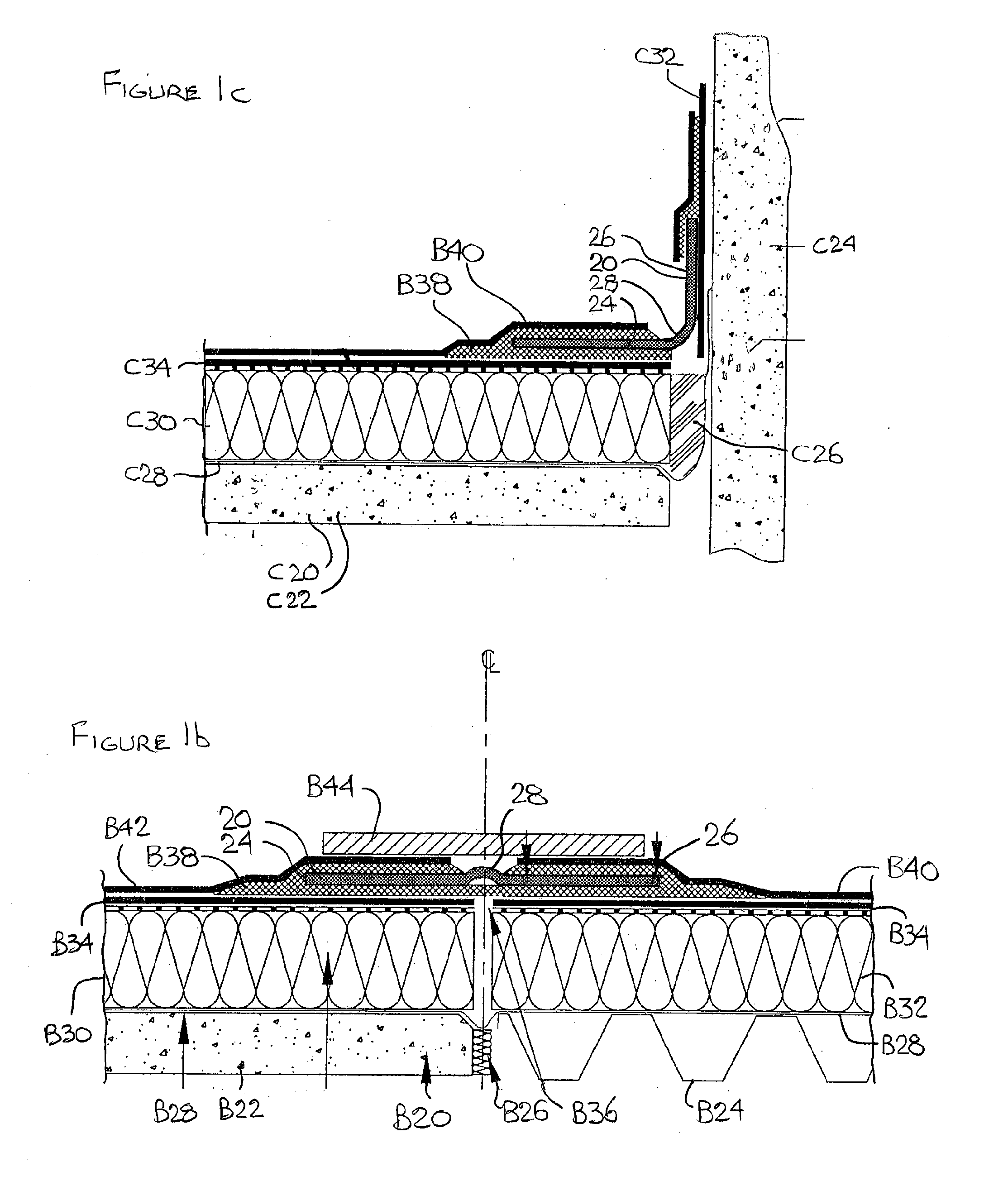
[0029]The description that follows, and the embodiments described therein, are provided by way of illustration of examples of particular embodiments of the principles, aspects or features of the present invention. These examples are provided for the purposes of explanation, and not of limitation, of those principles and of the invention. In the description, like parts are marked throughout the specification and the drawings with the same respective reference numerals. The drawings are generally to scale in plan view. However, in view of the aspect ratios of thickness to width, the thickness has been exaggerated or enlarged in some views for the purposes of clarity of illustration.

[0030]The terminology used in this specification is thought to be consistent with the customary and ordinary meanings of those terms as they would be understood by a person of ordinary skill in the art in North America. Following from decision of the Federal Circuit in Phillips v. A WH Corp., the Applicant ...


PUM


Abstract

An expansion joint has an elongated flat sheet of flexible and resilient polymeric material. The flat sheet has having a width and a length; upper and lower surfaces; and first and second edges. The sheet has selvage edges and a central gland. The selvage edges have a pair of parallel elongate first and second scrims. The scrims may be formed or embedded on each of the opposite surfaces along the length of the sheet. The rough strips on each surface bracket the elongated strip of bare surface of the gland. The sheet has an array of apertures located in one of the selvage edges. An additional array of apertures may be formed in the opposite selvage edge. The apertures pass through, but are not limited to passing through, the sheet and the strips.

Description

FIELD OF THE INVENTION [0001]The invention relates generally to rubber or polymeric waterproof expansion joints.BACKGROUND OF THE INVENTION [0002]Rubber expansion joints are often used in construction to help water proof roofs, slabs, and walls, thereby to protect the structure from effluent damage, which may typically be water damage. Traditionally, these expansion joints have included an elongated flat sheet of rubber, vinyl or some other flexible, resilient polymeric material. These expansion joints are usually laid over a joint between two walls or two sheets of waterproofing tiles or fabric. Expansion joints are typically secured to the surface of the joint by adhesive such as tar or the like.[0003]Rubber expansion joints may be present some challenges or disadvantages. For example, on hot summer days, the tar or adhesive used to bond the joint to the underlying substrate and to hold the joint in place may soften or weaken. This may result in the joint to becoming dislodged and...

Claims


Application Information

Patent Timeline
IPC IPC(8): E04B1/68
CPCE04B1/6809
Inventor ZIELONKA, KRZYSZTOF
Owner ZIELONKA KRZYSZTOF
Why Eureka
Try Eureka