Battery mounting structure for vehicle

Inactive Publication Date: 2010-12-09
FUJI JUKOGYO KK
View PDF91 Cites 152 Cited by
  • Summary
  • Abstract
  • Description
  • Claims
  • Application Information

AI Technical Summary

Benefits of technology

[0018](1) Since the sealing means is disposed above the outer peripheral frame and positioned further inside than the outer periphery of the outer peripheral frame in plan view, the outer peripheral frame protects the sealing means such that even when a lower portion of the vehicle body is sprayed with water from a vehicle wheel or a high-pressure car-washing machine, the water is unlikely to reach the sealing means. As a result, drenching of the battery can be prevented even when the battery box is mounted under the floor.
[0019](2) Since the guard portion for concealing the sealing means from the outside of the vehicle in cooperation with the outer peripheral frame is formed on the outer peripheral edge portion of at least one of the cover and the battery pan, the sealing means can be protected against water that passes through the outer peripheral frame. As a result, drenching of the battery can be prevented more reliably. A tongue-shaped end surface portion extending downward from a projecting end portion of the cover side flange, for example, may be used as the guard portion.
[0020](3) Since the sealing means in the front end portion of the battery box is disposed on the rear side of the cross member provided on the vehicle body so as to extend in the vehicle width direction, and a part of the outer peripheral frame is disposed under the gap between the cross member and the sealing means, the sealing means in the front portion of the battery box, which is more likely to be soaked with water during travel, can be protected by the cross member and the outer peripheral frame, thereby preventing drenching of the battery. Further, by providing the cross member, load transfer in the vehicle width direction can be performed efficiently and rigidity can be secured in the vehicle body

Problems solved by technology

Moreover, the height of the battery box is increased, and it is therefore difficult to secure cabin space

Method used


Image

  • Battery mounting structure for vehicle
  • Battery mounting structure for vehicle
  • Battery mounting structure for vehicle

Examples


Embodiment Construction

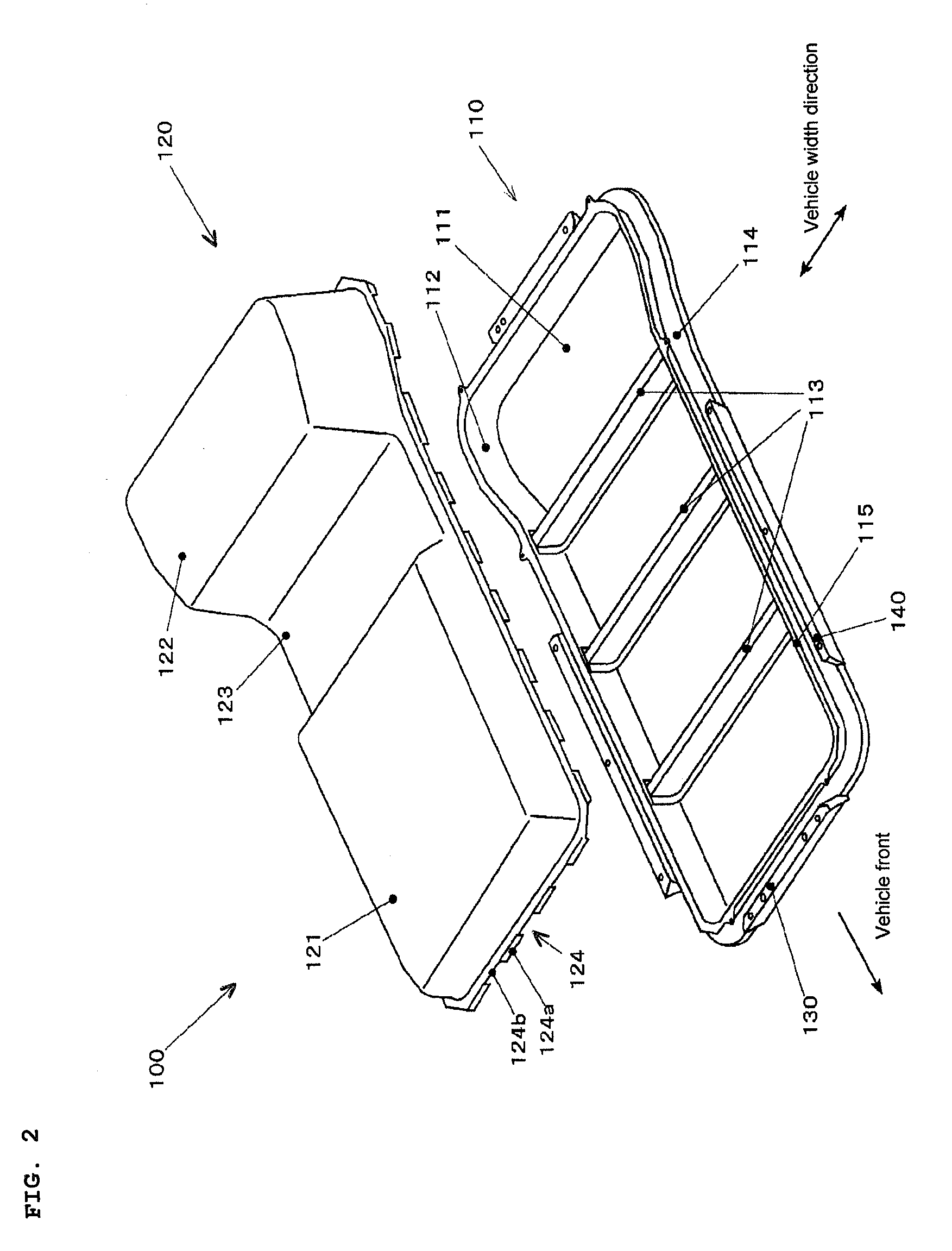
[0034]The present invention achieves the object of providing a battery mounting structure for a vehicle with which a battery is unlikely to be drenched even when the structure is disposed under a floor by having an outer peripheral frame project downward below a sealing portion formed between a battery pan and a cover constituting a battery box.

[0035]An embodiment of a battery mounting structure for a vehicle to which the present invention is applied will be described below. The battery mounting structure for a vehicle according to this embodiment is provided in a cabin under-floor portion of a vehicle such as a passenger car, for example.

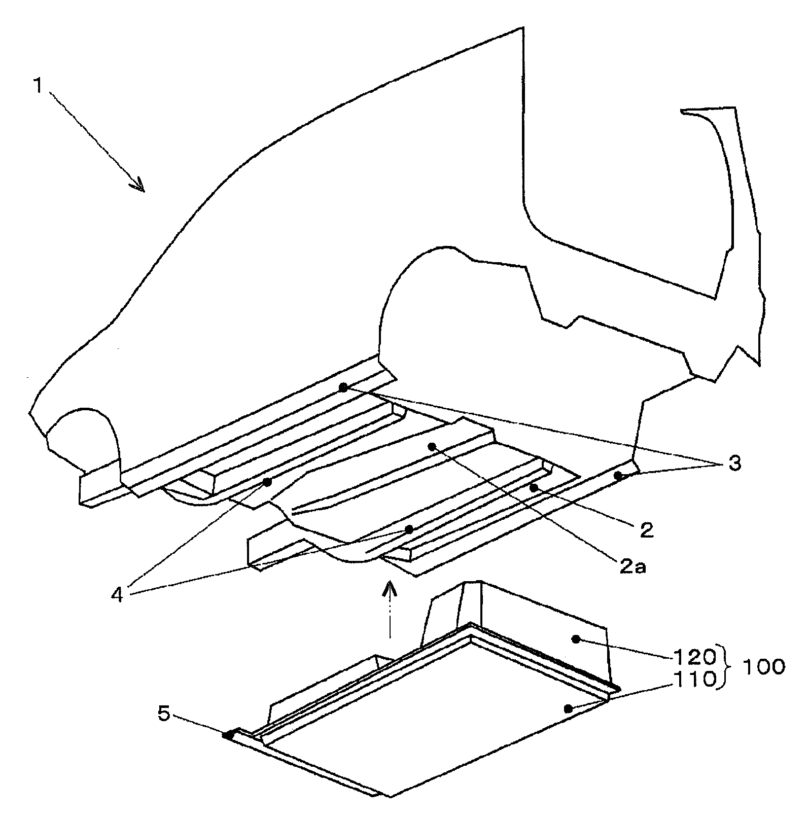
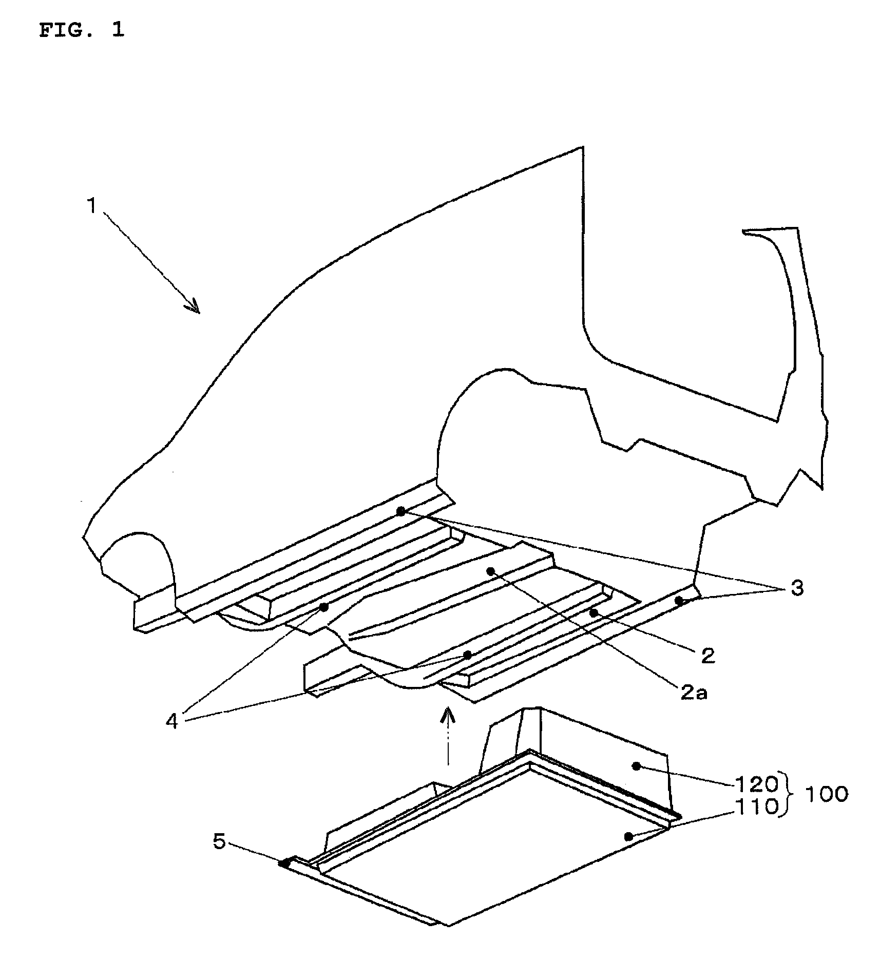
[0036]A vehicle 1 on which the battery mounting structure for a vehicle is mounted is a two-box type small passenger vehicle (a minivan), for example, and includes a floor panel 2, side sills 3, side frames 4, a cross member 5, and so on, wherein a battery box 100 is mounted in a suspended state on an under-floor side of the floor panel 2 and in a ...


PUM


Abstract

In a battery mounting structure for a vehicle that includes a battery box mounted on an under-floor side of a vehicle body floor, the battery box includes: a battery pan on which a battery is placed; an outer peripheral frame formed to project from an outer peripheral edge portion of the battery pan; a cover placed on the battery pan from above; and sealing means provided in a joint portion between the battery pan and the cover, wherein the sealing means is disposed above the outer peripheral frame and positioned further inside than an outer periphery of the outer peripheral frame in plan view.

Description

CROSS-REFERENCE TO RELATED APPLICATIONS[0001]The present application claims priority from Japanese Patent Application No. 2009-138064 filed on Jun. 9, 2009, and is hereby incorporated by reference in its entirety.BACKGROUND OF THE INVENTION[0002]1. Field of the Invention[0003]The present invention relates to battery mounting structures for vehicles, with which a battery can be mounted in a vehicle such as an electric vehicle or an electric hybrid vehicle.[0004]2. Description of the Related Art[0005]In a vehicle such as an electric vehicle or an engine / electric hybrid vehicle, a battery used as a travel power source is conventionally mounted in the vehicle, housed in a battery box serving as a protective container.[0006]For example, Japanese Unexamined Patent Application Publication No. 2006-335243 describes a power supply device for a vehicle in which a battery box that includes a battery cover and houses a plurality of battery modules is connected to a side frame of a vehicle body ...

Claims


Application Information

Patent Timeline
IPC IPC(8): B60R16/04
CPCB60K1/04B60K2001/0438Y02T10/705B60L11/1879Y02T10/7005B60L11/1877B60L50/64B60L50/66Y02T10/70
Inventor HASHIMOTO, TAKASHIYAMAMOTO, TOSHIYUKI
Owner FUJI JUKOGYO KK
Why Eureka
Try Eureka