Eureka AIR delivers breakthrough ideas for toughest innovation challenges, trusted by R&D personnel around the world.

Modified rotary type water supply device used for spray system

A water supply device and sprinkler system technology, applied in the direction of spraying devices, spraying devices, etc., can solve the problems of reduced service life, damage to the rotating shaft, and limited thrust, so as to improve the service life, ensure normal operation, and increase the thrust of the impeller. Effect

Inactive Publication Date: 2013-01-23
View PDF7 Cites 0 Cited by
  • Summary
  • Abstract
  • Description
  • Claims
  • Application Information

AI Technical Summary

Problems solved by technology

[0002] On September 2, 2009, the State Intellectual Property Office published a Chinese invention with application number 200910037408.5, a rotary water supply device used for improvement in sprinkler systems. This structure can effectively push water to high places, and Spread evenly through the rotating nozzle, but due to its design flaws, water accumulates inside the main body, which damages the rotating shaft and reduces its service life; and because of the simple structure of the blades and the large distance between the impellers, the force of the water flow between the impellers cancels out. , cannot achieve consistent thrust from bottom to top, so its thrust is limited

Method used


Image

  • Modified rotary type water supply device used for spray system
  • Modified rotary type water supply device used for spray system
  • Modified rotary type water supply device used for spray system

Examples


Embodiment Construction

[0019] The present invention will be described in further detail below in conjunction with the accompanying drawings.

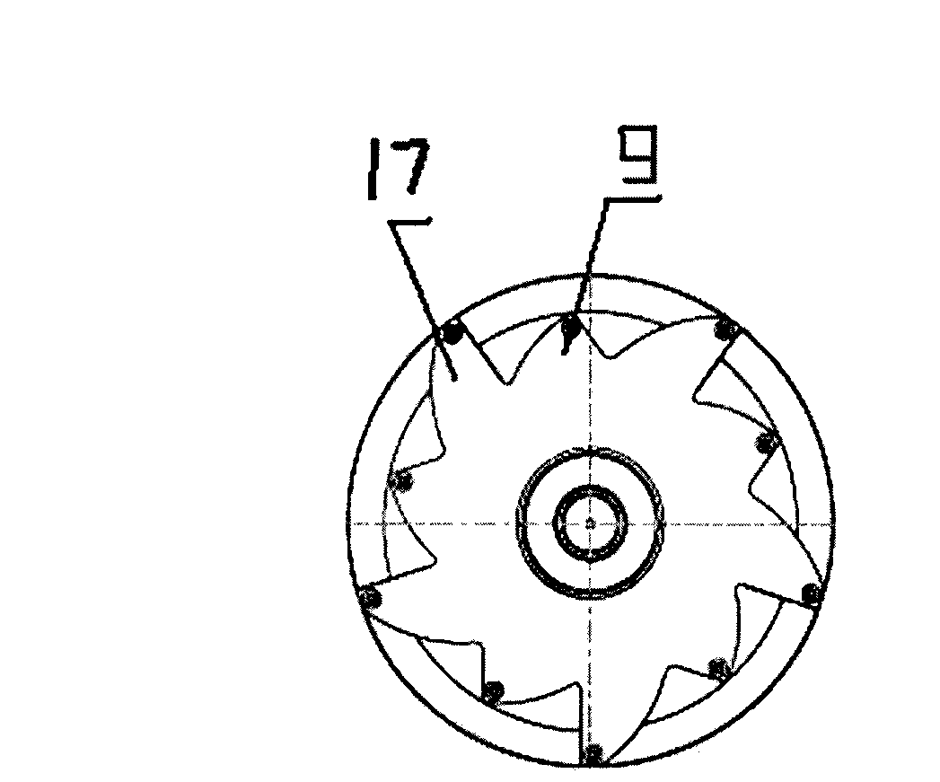
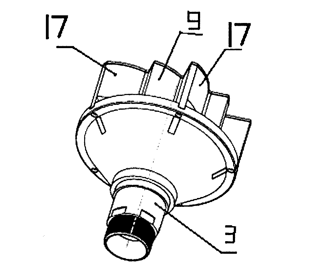
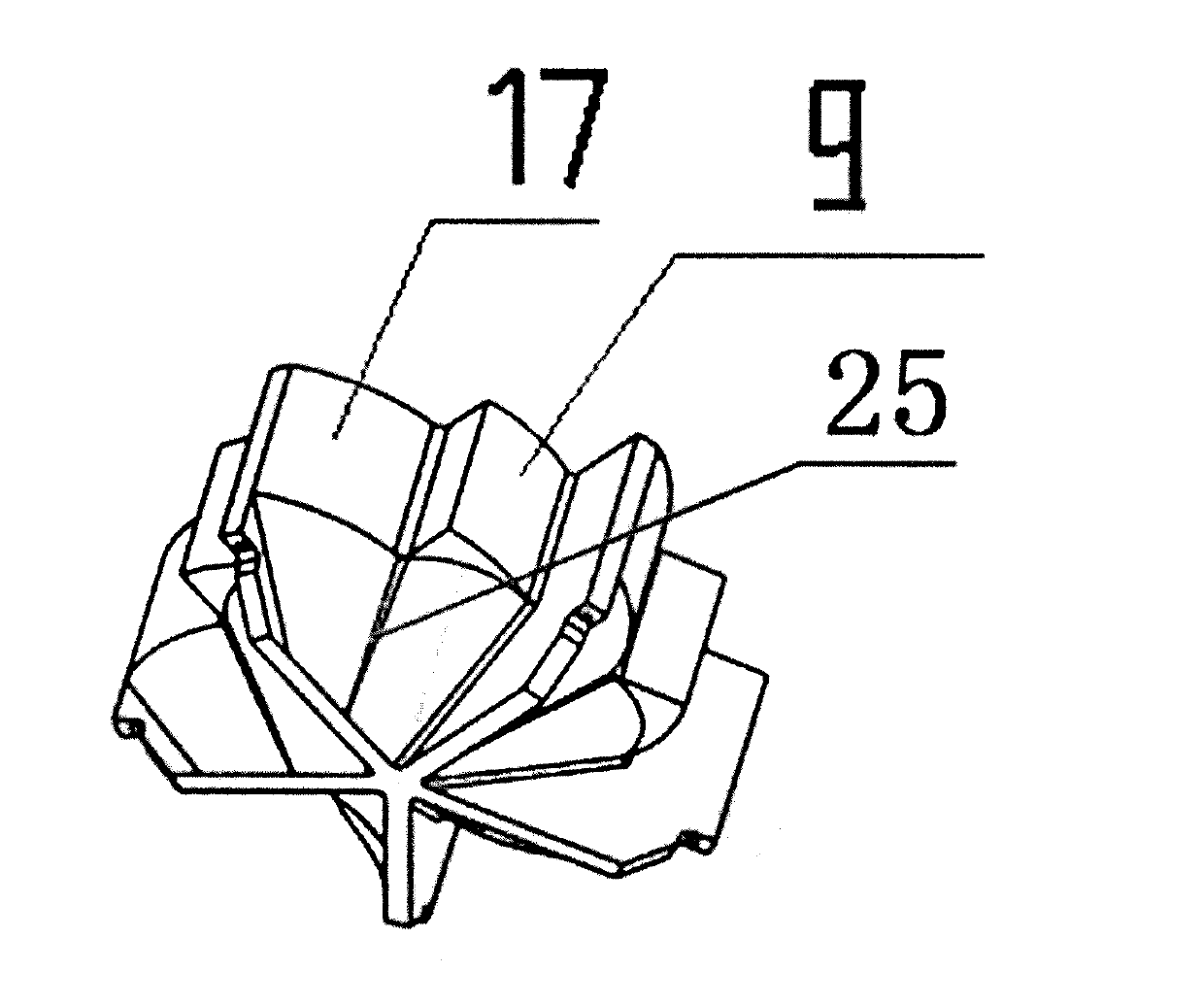
[0020] Such as Figure 1 to Figure 7 As shown, an improved rotary water supply device for spraying systems, the water supply device includes a main body 1, a water chamber is arranged in the main body, and a water inlet pipe 2 communicating with the water pump is arranged on the water chamber, and the water chamber A rotating impeller structure is provided, the upper end of the rotating impeller structure is integrated with a water pipe 15, and the central axis 18 is set at the center of the lower end. The rotating impeller structure includes a main impeller 17. The water pipe passes through the upper bearing seat 5, and the lower end of the main body is arranged in cooperation. The lower bearing housing 6, the rotating impeller structure is divided into an inverted umbrella-shaped upper impeller 10, a middle impeller 11 and a lower impeller 12, wherein the i...


PUM


Abstract

The invention relates to a water supply device, in particular to a modified rotary type water supply device used for a spray system. The water supply device comprises a main body (1), wherein a water cavity is arranged in the main body, the water cavity is provided with a water inlet pipe (2) connected with the water pump, a rotary impeller structure is arranged in the water cavity, a water pipe (15) is integrally arranged on the upper end of the rotary impeller structure, a center shaft (18) is arranged on the lower end of the rotary impeller structure, the rotary impeller structure (3) comprises main impellers (17), the water pipe penetrates through an upper bearing seat (5), the lower end of the main body is matched with a lower bearing seat (6), the water supply device is characterized in that the rotary impeller structure is divided into a reverse umbrella-shaped upper impeller (10), a middle impeller (11) and a lower impeller (12), wherein the reverse umbrella-shaped upper impeller (10), the middle impeller (11) and the lower impeller (12) are vertically connected through screws so as to form an integrated structure, an auxiliary impeller (9) is arranged between every two main impellers (17), a projection part on the upper end of the upper bearing seat (5) is provided with first drainage holes (7) which are arranged at an equal distance, and the lower bearing seat (6) is provided with second drainage holes (8) which are arranged at an equal distance. By adopting the technical scheme, the water supply device has the advantages of reasonable design, easiness in discharging ponding in the water cavity, long service life of the bearing, and strong impeller thrust.

Description

technical field [0001] The invention relates to a water supply device, in particular to an improved rotary water supply device used in a sprinkler system. Background technique [0002] On September 2, 2009, the State Intellectual Property Office published a Chinese invention with application number 200910037408.5, a rotary water supply device used for improvement in sprinkler systems. This structure can effectively push water to high places, and Spread evenly through the rotating nozzle, but due to its design flaws, water accumulates inside the main body, which damages the rotating shaft and reduces its service life; and because of the simple structure of the blades and the large distance between the impellers, the force of the water flow between the impellers cancels out. , cannot achieve consistent thrust from bottom to top, so its thrust is limited. Contents of the invention [0003] Aiming at the defects of the Chinese invention with the application number 20091003740...

Claims


Application Information

Patent Timeline
IPC IPC(8): B05B1/26B05B1/34B05B1/00
Inventor 丘新贵
Why Eureka
Eureka Blog
Learn More