Breathable element for lighting of vehicle

Inactive Publication Date: 2019-10-31
JUTE INDS
47 Cites 1 Cited by

AI-Extracted Technical Summary

Problems solved by technology

However, dust or water outside may enter the devices via the ventilation holes to damage the devices or shorten its servi...

Method used

[0018]Specifically, the outer surface of the outer cylinder 22 contacts the inner surface of the housing 10 completely, so larger friction is provided to position the cylinder 20 inside the housing 10. Thus, the housing 10 is difficult to fall off from the cylinder 20...

Benefits of technology

[0004]The main object of the present invention is to provide a breathable element for light...

Abstract

A breathable element for lighting of vehicle includes a housing, a cylinder, and a breathable film. The housing has a peripheral wall and a bottom to enclose a receiving room. The peripheral wall has a positioning structure at the opening end. The bottom has a protruding structure. The cylinder includes an inner cylinder and an outer cylinder. The inner cylinder is connected with the outer cylinder via plural connection portions arranged spacedly. An air channel is defined between any two adjacent connection portions and extends axially. The inner cylinder is axially formed with a channel. The cylinder abuts against the protruding structure. The cylinder is received in the receiving room so that the channel communicates the air channel. The cylinder is prevented from leaving the housing freely by the positioning structure. The breathable film is disposed on an end of the inner cylinder inside the housing.

Application Domain

Technology Topic

Image

  • Breathable element for lighting of vehicle
  • Breathable element for lighting of vehicle
  • Breathable element for lighting of vehicle

Examples

  • Experimental program(1)

Example

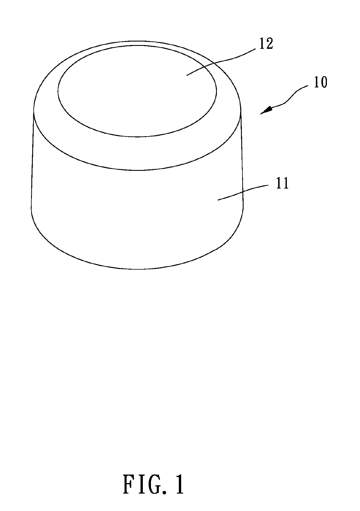
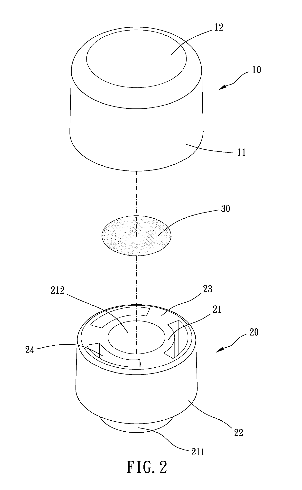
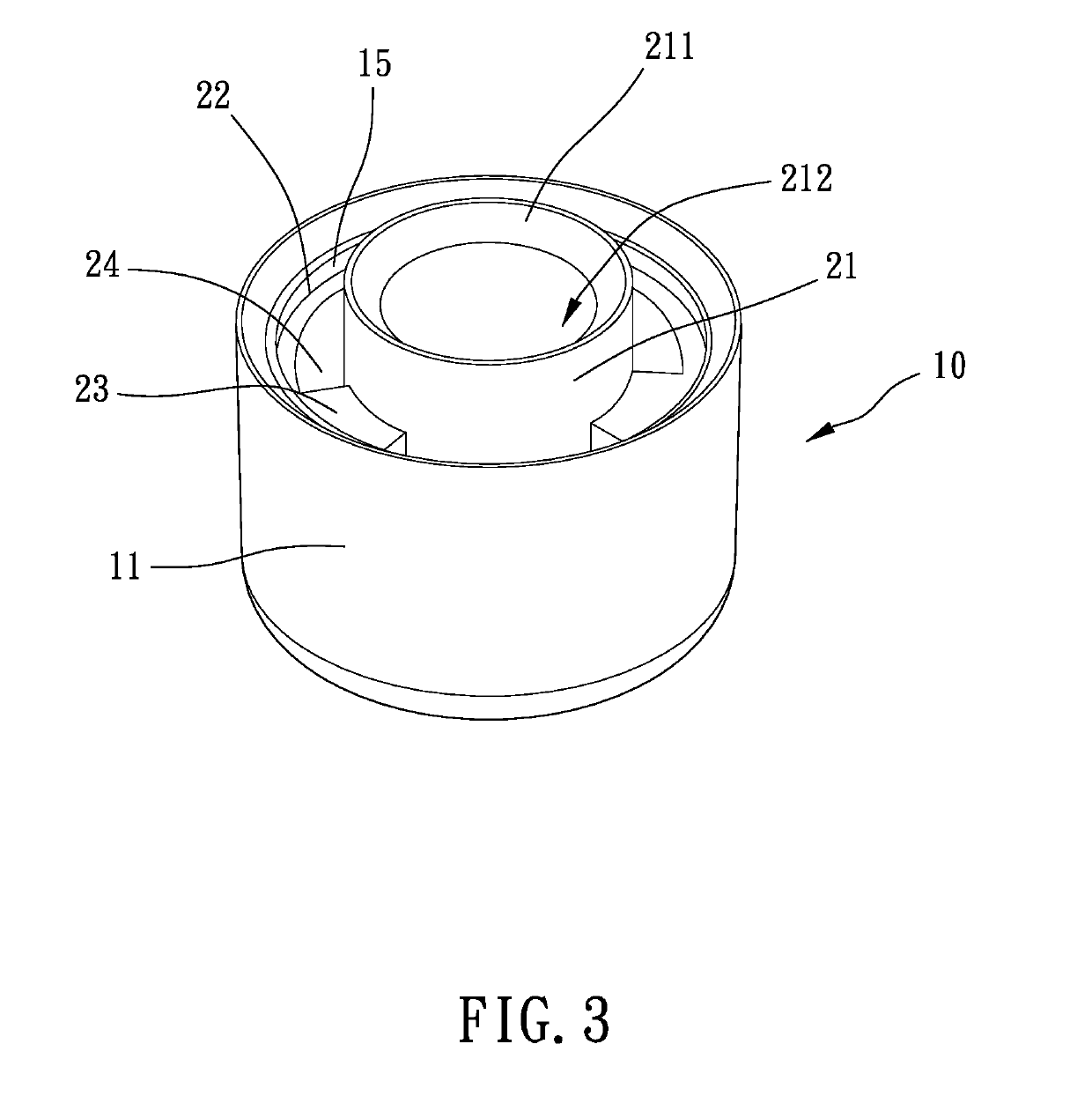
[0014]Please refer to FIG. 1 to FIG. 7, the breathable element for lighting of vehicle of the present invention includes a housing 10, a cylinder 20, and a breathable film 30.
[0015]The housing 10 is cylinder-shaped and has a peripheral wall 11 and a bottom 12. The peripheral wall 11 and the bottom 12 enclose a receiving room 13. The peripheral wall 11 is formed with a positioning structure 15 at an end thereof remote from the bottom 12. The positioning structure 15 is protruded radially and inward. The bottom 12 has at least one protruding structure 14. The cylinder 20 is made of elastic material and includes an inner cylinder 21 and an outer cylinder 22. The inner cylinder 21 is located in the outer cylinder 22 and connected with the outer cylinder 22 via a plurality of connection portions 23 arranged spacedly. An air channel 24 is defined among any two adjacent the connection portions 23, the inner cylinder 21, and the outer cylinder 22. The air channel 24 extends along an axial direction of the cylinder 20. An end of the inner cylinder 21 is an engaging portion 211. The inner cylinder 21 is axially formed with a channel 212. An end of the cylinder 20 remote from the engaging portion 211 abuts against the protruding structure 14, and the cylinder 20 is received in the receiving room 13 so that the channel 212 communicates the air channel 24 due to the protruding structure 14. The cylinder 20 is positioned by the positioning structure 15 to be prevented from leaving the housing 10 freely. The breathable film 30 is disposed on an end of the inner cylinder 21 remote from the engaging portion 211. Air is able to pass through the breathable film 30, but liquid is blocked by the breathable film 30.
[0016]In the present embodiment, the positioning structure 15 is an annular flange protruded radially and surrounding the housing 10 circumferentially. The protruding structure 14 is a stepped portion formed at a juncture of the peripheral wall 11 and the bottom 12 and surrounding the housing 10 circumferentially. Preferably, an inner diameter of the stepped portion is larger than an outer diameter of the inner cylinder 21 but smaller than an outer diameter of the outer cylinder 22. Besides, an outer diameter of the outer cylinder 22 is equal to or slightly larger than an inner diameter of the housing 10. Thus, the elastic cylinder 20 can be positioned in the housing 10 by tight-fit. The engaging portion 211 is located outside the outer cylinder 22. In addition, the cylinder 20 preferably includes three the connection portions 23 and three the air channels 24. A circumferential length of each of the connection portions 23 is smaller than a circumferential length of each of the air channels 24.
[0017]In use, the engaging portion 211 is inserted into a connector of a device 40. The interior of the device 40 communicates the exterior via the channels 212, the receiving room 13, and the air channels 24. However, the channels 212 are disposed with the breathable film 30, so only gas can move between the interior and the exterior of the device 40. Liquid is blocked from entering the interior of the device 40 from the exterior. Therefore, the present invention is good at water-proofing and ventilation.
[0018]Specifically, the outer surface of the outer cylinder 22 contacts the inner surface of the housing 10 completely, so larger friction is provided to position the cylinder 20 inside the housing 10. Thus, the housing 10 is difficult to fall off from the cylinder 20.
[0019]Thereby, the present invention has a simple structure and easy installation to protect electronic devices or machines from water but good at ventilation. In addition, the breathable film is protected by the housing so that the present invention is more durable.

PUM

no PUM

Description & Claims & Application Information

We can also present the details of the Description, Claims and Application information to help users get a comprehensive understanding of the technical details of the patent, such as background art, summary of invention, brief description of drawings, description of embodiments, and other original content. On the other hand, users can also determine the specific scope of protection of the technology through the list of claims; as well as understand the changes in the life cycle of the technology with the presentation of the patent timeline. Login to view more.

Similar technology patents

Multifunctional haze protection mask

Owner:NINGBO BAOZHONG EMERGENCY TECH CO LTD

Absorption type planting method for scrophularia ningpoensis

InactiveCN106613085AReduces the chance of standing waterGood ventilationSuperphosphatesFertilising methodsFertilizerScrophularia aquatica
Owner:DAOZHEN GELAO & MIAO AUTONOMOUS COUNTY RUIFA AGRI TECH DEV CO LTD

Classification and recommendation of technical efficacy words

  • Good ventilation

Self-Closing Ventilation Insert and Method for Producing it

ActiveUS20090203275A1Rapid and inexpensive productionGood ventilationButtonsWeft knittingPatent applicationEngineering
Owner:IQTEX PATENTVERWALTUNG UG HAFTUNGSBESCHRANKT

Seedling growing method for lemons

Owner:玉林市武宁油茶种植有限公司

Turtle medium-free hatching method and device

Owner:FISHERIES RES INST ANHUI ACAD OF AGRI SCI +1
Why Eureka
Try Eureka