Image forming apparatus capable of forming high quality superimposed image

a technology of image forming apparatus and superimposed image, which is applied in the direction of electrographic process apparatus, instruments, optics, etc., can solve problems such as intracyclical fluctuation

Inactive Publication Date: 2010-12-09
RICOH KK
View PDF47 Cites 45 Cited by
  • Summary
  • Abstract
  • Description
  • Claims
  • Application Information

AI Technical Summary

Problems solved by technology

However, intracyclical fluctuation in rotational velocity of the rollers which rotatably sus

Method used


Image

  • Image forming apparatus capable of forming high quality superimposed image
  • Image forming apparatus capable of forming high quality superimposed image
  • Image forming apparatus capable of forming high quality superimposed image

Examples


first embodiment

[0086]Further, toner remaining and removed from the surfaces of the photo-conductive members 11Y to 11K of the printer of this embodiment can be collected by the drum cleaning devices and are used again by the developing devices of respective colors as in the conventional system. In such a situation, for the above-mentioned reason as applied to the first embodiment, the K use image formation unit 1K, e.g., the K-use direct transfer nip is arranged upstream of the secondary transfer nip, so that the toner does not mix in the K use developing device, and color tone of the image (i.e., a K toner image) formed in the image formation unit 1K does not change even as time elapses.

[0087]Also in this embodiment, the printing sheet P is carried and conveyed by the direct transfer belt 13 through the direct transfer nip and the secondary transfer nip. Thus, regardless of that the direct transfer nip is arranged either downstream or upstream of the secondary transfer nip, the printing sheet P c...

third embodiment

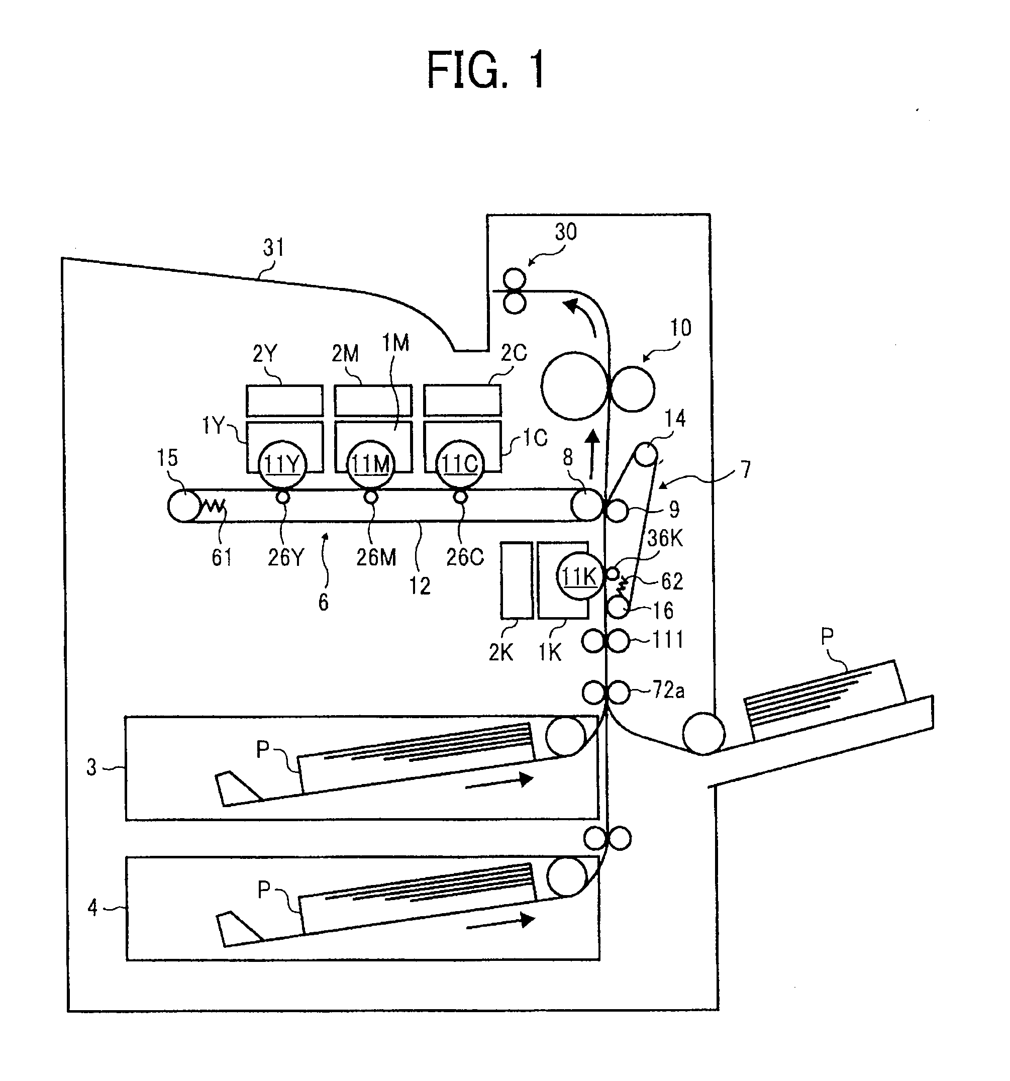
[0091]Now, a color laser printer (herein after reference to as a printer) serving as an image forming apparatus employing an electro photographic system is described with reference to FIG. 11.

As shown, the fundamental configuration of the printer of this embodiment is almost the same as that of the first embodiment.

second embodiment

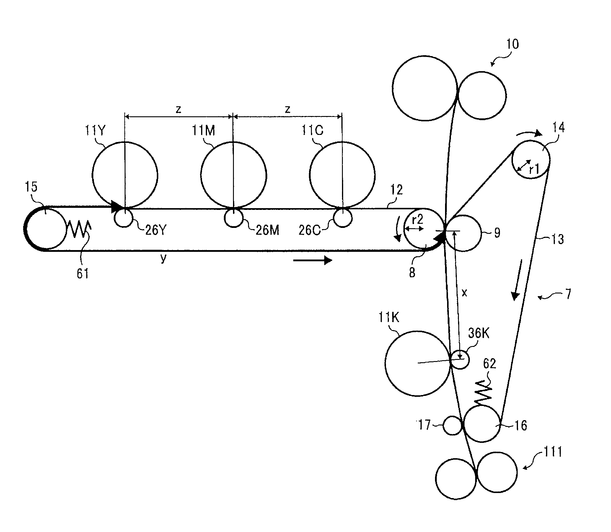
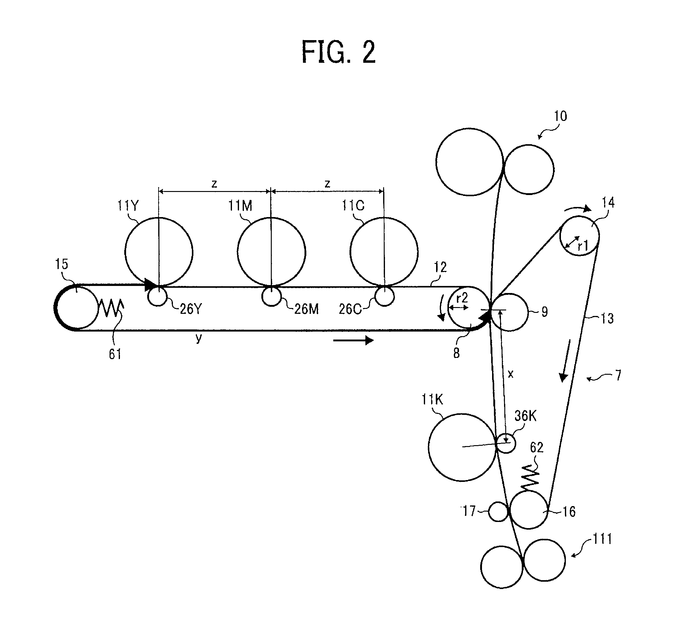
[0092]Specifically, different from the above-mentioned second embodiment, the printing sheet P is carried and conveyed by a photo-conductive member 11K and a transfer roller 36K driven rotated by a drive source including a drive motor, not shown, through the direct transfer nip and the secondary transfer nip while applying thereto a conveyance force via the transfer roller 36K in a printer of this embodiment.

[0093]In this system, the printing sheet P is conveyed between the secondary transfer and the direct transfer positions by a conveyance force applied from the transfer roller 36K in the direct transfer nip. Thus, the conveyance velocity of the printing sheet P fluctuates in a rotation cycle of the transfer roller 36K due to eccentricity of the transfer roller 36K. Thus, if a velocity of the printing sheet P fluctuates, and a phase thereof is different between the direct transfer and secondary transfer nips, displacement occurs on the Y to K toner images transferred onto the prin...


PUM


Abstract

An image forming apparatus includes a primary transfer device that primarily transfers a first image from a first image bearer onto a first belt unit at a primary transfer position, a secondary transfer device that secondarily transfers the first image from the first belt unit onto a printing medium at a secondary transfer position, and a direct transfer device that directly transfers a second image from a second image bearer onto the printing medium at a direct transfer position.
A second belt unit is rotatably suspended by plural second rollers and carries and conveys the printing medium through the direct transfer position and the secondary transfer position. An interval between the direct transfer position and the secondary transfer position is prescribed natural number times of a circumference of one of the plural second rollers, which fluctuates a velocity of the second belt unit.

Description

CROSS-REFERENCE TO RELATED APPLICATIONS[0001]This application claims priority under 35 USC §119 to Japanese Patent Application No. 2009-133931, filed on Jun. 3, 2009, the entire contents of which are herein incorporated by reference.BACKGROUND OF THE INVENTION[0002]1. Field of the Invention[0003]The present invention relates to an image forming apparatus, such as a printer, a facsimile, a copier, etc.[0004]2. Discussion of the Background Art[0005]Conventionally, a color image forming apparatus that includes plural image formation sections for forming color images of component colors including black is known.[0006]As described in the Japanese Patent Application Laid Open No. 2006-201743, there are provided, in an image forming apparatus, a direct transfer position where a black color image formed in a black image formation section is directly transferred and a secondary transfer position where the other color images primary transferred onto an intermediate transfer belt from the imag...

Claims


Application Information

Patent Timeline
IPC IPC(8): G03G15/01
CPCG03G15/0131G03G15/167G03G15/0178
Inventor MIURA, YOHEIAMANAI, KOUJIEBARA, JOHUCHIDA, TOSHIYUKISUGITA, NARUMISUGIYAMA, KEISUKETOMITA, KENJIYAMAZAKI, KIMIHARU
Owner RICOH KK
Why Eureka
Try Eureka