High-precision optical tiny thrust measurement system based on two-beam interference principle

A double-beam interference and measurement system technology, which is applied in the field of engine micro-thrust measurement devices and engine thrust measurement devices, can solve the problems of high friction-free requirements at the joints of components, a large number of sensors, complex systems, etc., and achieve easy replacement and maintenance. Measuring Precise, Wide-Source Effects

Inactive Publication Date: 2015-01-14
BEIHANG UNIV
View PDF5 Cites 17 Cited by
  • Summary
  • Abstract
  • Description
  • Claims
  • Application Information

AI Technical Summary

Problems solved by technology

However, the system based on this principle is relatively complex, wi

Method used


Image

  • High-precision optical tiny thrust measurement system based on two-beam interference principle
  • High-precision optical tiny thrust measurement system based on two-beam interference principle
  • High-precision optical tiny thrust measurement system based on two-beam interference principle

Examples


Embodiment Construction

[0037] The present invention will be further described below in conjunction with the accompanying drawings.

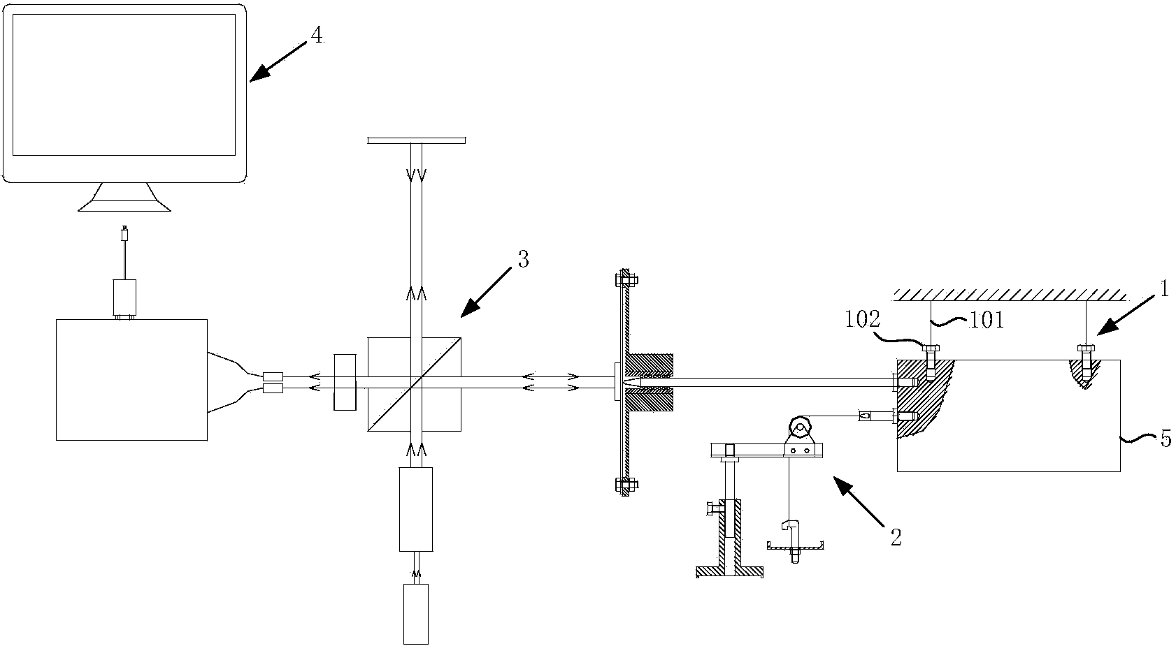
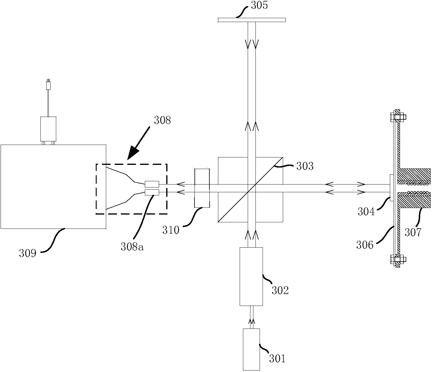
[0038] The high-precision optical micro-thrust measurement system based on the principle of double-beam interference of the present invention includes an engine suspension assembly 1, a thrust calibration assembly 2, a thrust measurement optical system 3 and a computer 4, such as figure 1 shown.

[0039] The engine suspension assembly 1 includes a suspension bolt 101 and a suspension fishing line 102, which are used to suspend the engine 5 to be measured on a fixed surface; wherein, the suspension studs 101 are fixedly mounted on the side walls at the front and rear ends of the engine 5 to be measured, respectively The suspension of the engine 5 to be measured is realized by fixing the hanging fishing line 102 to the installation surface.

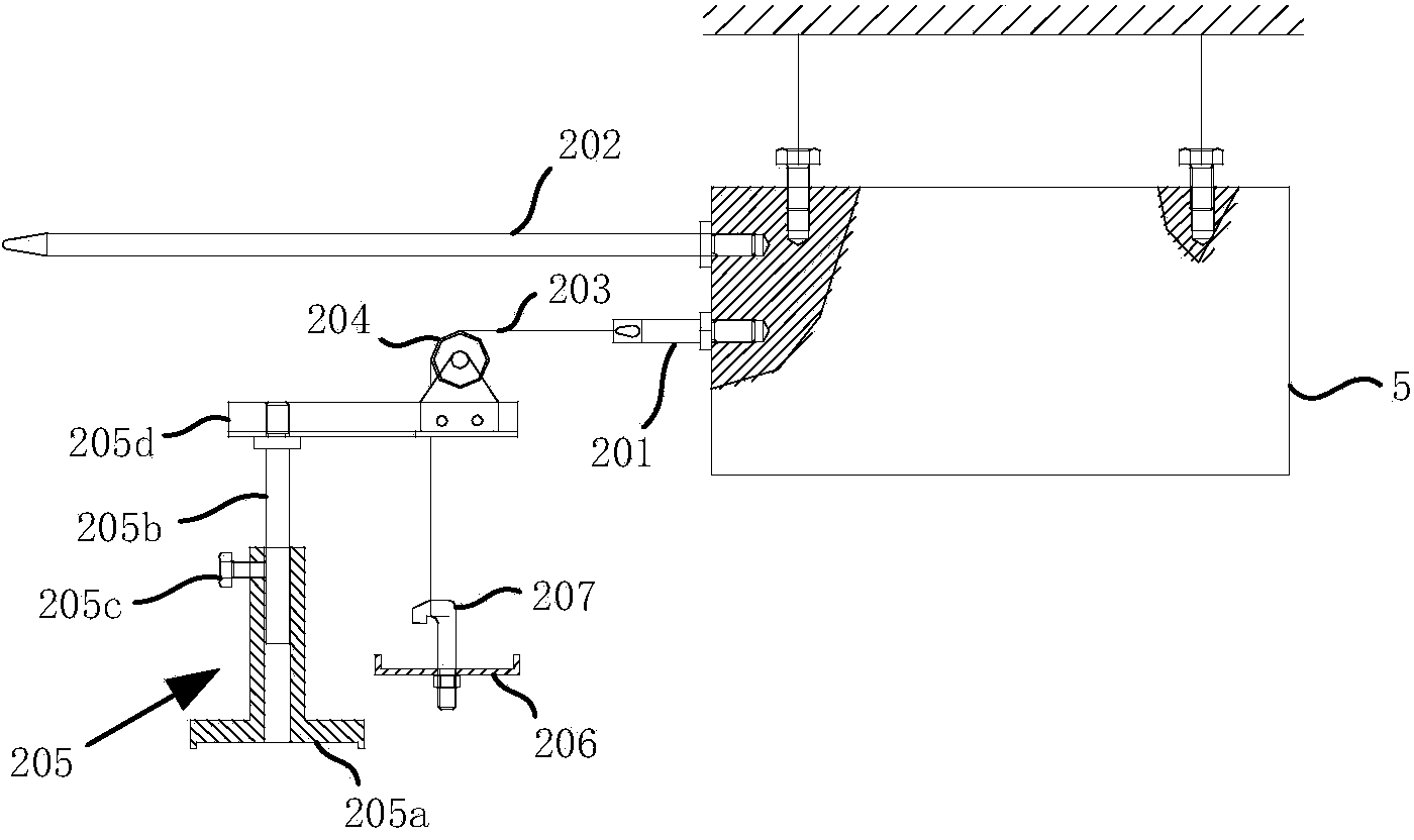
[0040] The thrust calibration assembly 2 includes a calibration center rod 201, a push rod 202, a calibration fishing line 203, a...


PUM


Abstract

The invention discloses a high-precision optical tiny thrust measurement system based on a two-beam interference principle. The high-precision optical tiny thrust measurement system comprises an engine suspension assembly, a thrust calibration assembly and a thrust measurement optical system. The thrust measurement optical system is used for generating interference fringes; an engine to be measured is hoisted through the engine suspension assembly, weights are placed on a weight disc in the thrust calibration assembly to generate thrust, and the thrust of the engine to be measured is simulated. The thrust is applied to a deformation membrane to enable the deformation membrane to deform, and the number of screwing and unscrewing turns of the interference fringes is changed. The variable quantity of the number of the screwing and unscrewing turns of the interference fringes is counted, and a thrust-counted number curve is generated by a computer to serve as a calibration curve. The number of the screwing and unscrewing turns of the interference fringes can also be changed by the thrust generated by the engine to be measured and is input into the computer after being counted by a counting device, a counted number-time curve is generated, the calibration curve is further used in a cooperation mode, and a thrust-time curve can be obtained. The high-precision optical tiny thrust measurement system has the advantages that sensors needed by measurement are few, the structure is simple, reliability is high, and measurement is accurate.

Description

technical field [0001] The invention belongs to the field of aerospace engines, and relates to an engine micro-thrust measuring device, specifically, an engine thrust measuring device with a micro-thrust measuring and calibration component for measuring 1 μN to 1N thrust. Background technique [0002] Thrust measurement experiment is the most direct and effective way to assess rocket engine, and thrust is one of the most important measurement parameters in measurement experiment. Only by obtaining the actual measured thrust can the actual performance parameters of the engine be obtained, and then the design and development of the engine can be completed. [0003] In the field of aerospace, the thrust less than or equal to 1N is generally called micro-thrust. At present, there are many measurement methods for micro-reasoning, such as target method, balance method, pendulum method, and optical method. Most of the current popular methods are based on the principle of balance ...

Claims


Application Information

Patent Timeline
IPC IPC(8): G01L1/24
Inventor 贺碧蛟黄子惟万屹仑田松岩刘乙君石庆利
Owner BEIHANG UNIV
Why Eureka
Try Eureka