LED module fabrication method

Inactive Publication Date: 2010-12-09
KWO GER METAL TECH
View PDF1 Cites 26 Cited by
  • Summary
  • Abstract
  • Description
  • Claims
  • Application Information

AI Technical Summary

Benefits of technology

[0015]The LED module fabrication method further comprises a sub-step of forming a locating groove on the bottom wall of the packing cup around the circuit substrate f

Problems solved by technology

In order to eliminate aging of the packaging resin E, a glass lens used and directly bonded to the LED chip A. However, directly bonding a glass lens to the LED chip A cannot eliminate the problem of existence of a gap in between the glass lens and the LED chip A. The presence of

Method used


Image

  • LED module fabrication method
  • LED module fabrication method
  • LED module fabrication method

Examples


Embodiment Construction

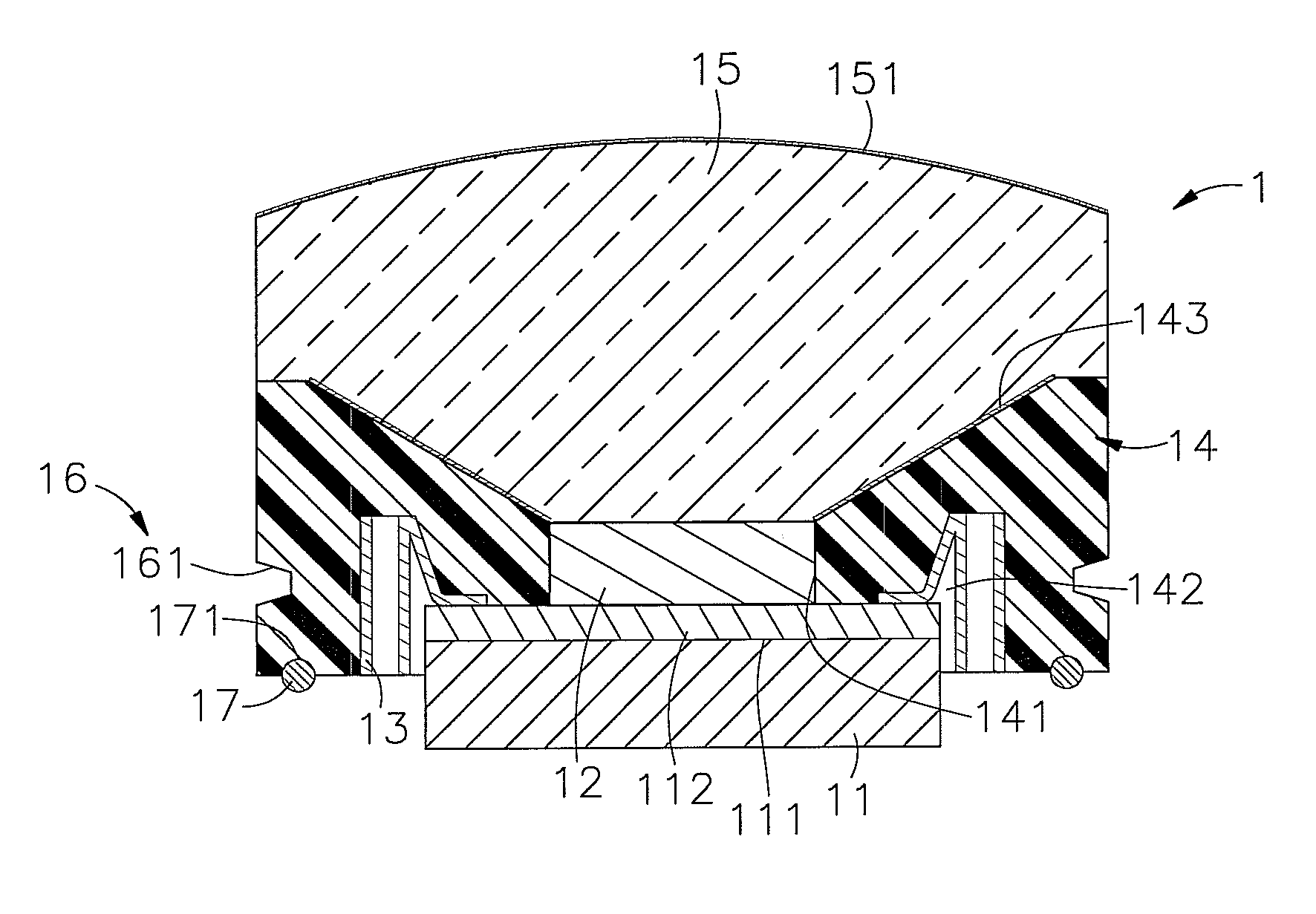
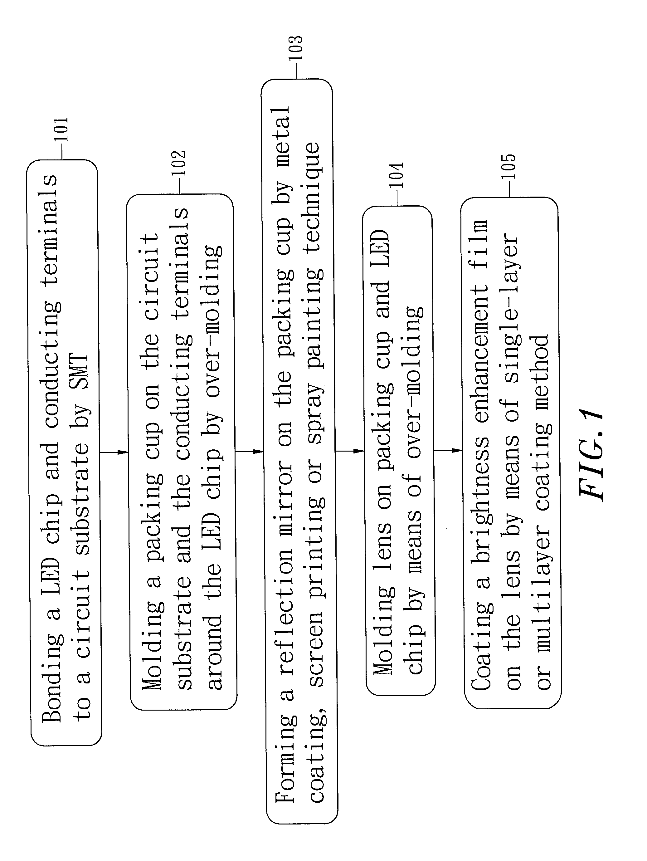
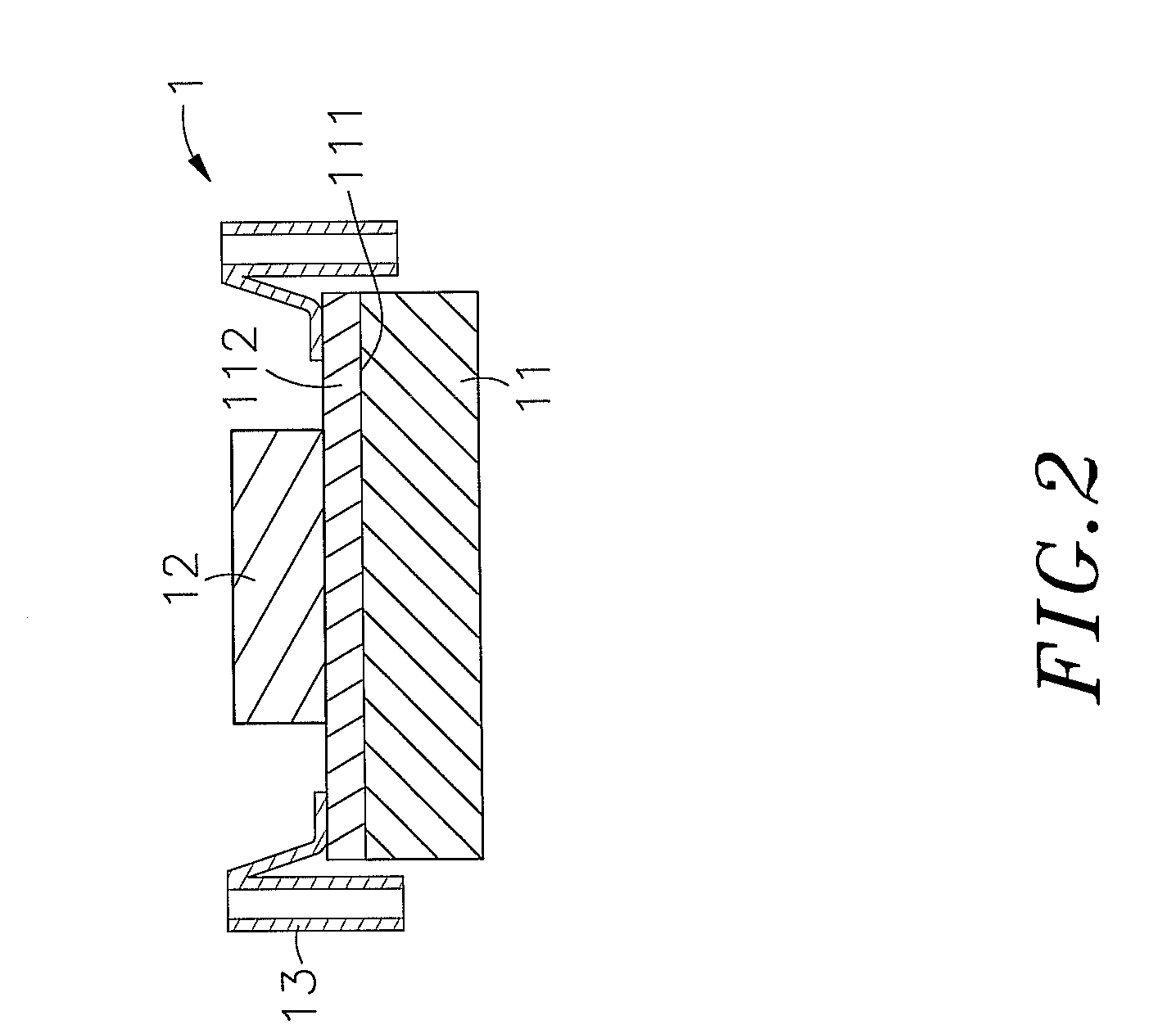
[0025]Referring to FIGS. 1˜5, a LED module fabrication method in accordance with the present invention is shown comprising the steps of:[0026](101) Bonding, where at least one LED (light emitting diode) chip 12 and a plurality of conducting terminals 13 are bonded to a circuit substrate 11 for LED module 1 by SMT (surface mount technology) or through-hole technology;[0027](102) Injection molding, where a packing cup 14 is molded on the circuit substrate 11 and the conducting terminals 13 around the LED chip 12 by over-molding, having a top opening 141 and a bottom opening 142 through which the LED chip 12 and the conducting terminals 13 are exposed to the outside;[0028](103) Mirror finishing, wherein a reflection mirror 143 is formed on the surface of the top opening 141 of the packing cup 14 by means of a metal coating, screen printing or spray painting technique for reflecting light emitted by the LED chip 12;[0029](104) Secondary injection molding, where a lens 15 is molded on th...


PUM


Abstract

A method of fabricating a LED module by: bonding one or multiple LED chips and multiple conducting terminals to a circuit substrate, and then molding a packing cup on the circuit substrate over by over molding for enabling the LED chip(s) and the conducting terminals to be exposed to the outside of the packing cup, and then molding a lens on the packing cup and the LED chip(s) by over-molding. By means of directly molding the lens on the packing cup and the LED chip(s), no any gap is left in the lens, avoiding deflection, total reflection or light attenuation and enhancing luminous brightness and assuring uniform distribution of output light.

Description

[0001]This application claims the priority benefit of Taiwan patent application number 098118434, filed on Jun. 3, 2009.BACKGROUND OF THE INVENTION[0002]1. Field of the Invention[0003]The present invention relates to a method for fabricating LED modules and more particularly, to such a LED module fabrication method, which employs an over molding technique to primarily mold a packing cup on a circuit substrate around a LED chip and then to secondarily mold a lens on the LED chip and the packing cup, so that no any gap is left in the lens, avoiding deflection, total reflection or light attenuation.[0004]2. Description of the Related Art[0005]Many different lighting fixtures using different light-emitting techniques are commercially available. Nowadays, LED (light emitting diode) has been intensively used in embedded lamps, head lamps and many other different lighting fixtures for the advantages of excellent photoelectric conversion efficiency, constant wavelength, adjustability of lum...

Claims


Application Information

Patent Timeline
IPC IPC(8): H01L21/56
CPCH01L33/486H01L33/54H01L33/62H01L2224/48091H01L2933/005H01L2924/00014
Inventor LIN, HSUAN-CHIH
Owner KWO GER METAL TECH
Why Eureka
Try Eureka