
Twist Drill With Negative Axial Rake Transition Between The Lip And The Secondary Cutting Edge

a technology of axial rake and secondary cutting edge, which is applied in the field of twist drill, can solve the problems of thermal degradation of the surface of the drill point, cutting operation,

Active Publication Date: 2010-12-16
KENNAMETAL INC
View PDF43 Cites 22 Cited by
  • Summary
  • Abstract
  • Description
  • Claims
  • Application Information

AI Technical Summary

Benefits of technology

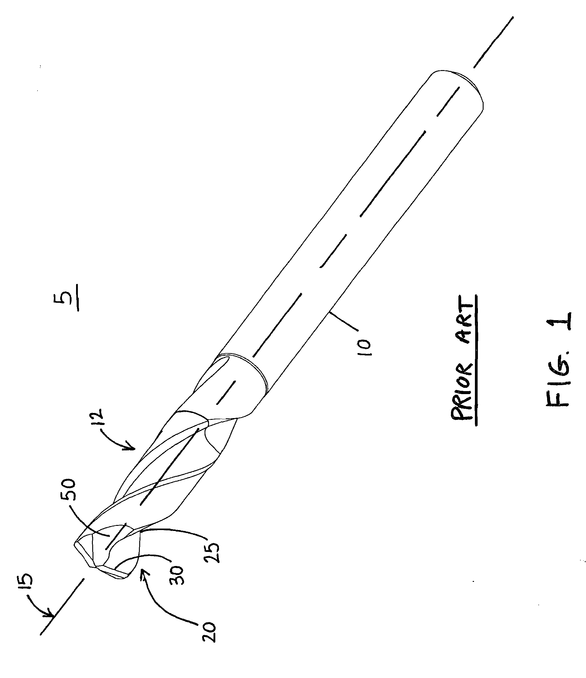
[0011]FIG. 1 is prior art and is a perspective view of a twist drill having a conventional drill point;

Problems solved by technology

In particular, major surfaces of the drill point result through the fabrication of the flute and an associated gash adjacent to the flute.
Not only does this built-up edge hinder the cutting operation but, furthermore, acts as a source of concentrated heat which over time thermally degrades the surface of the drill point.

Method used


Image

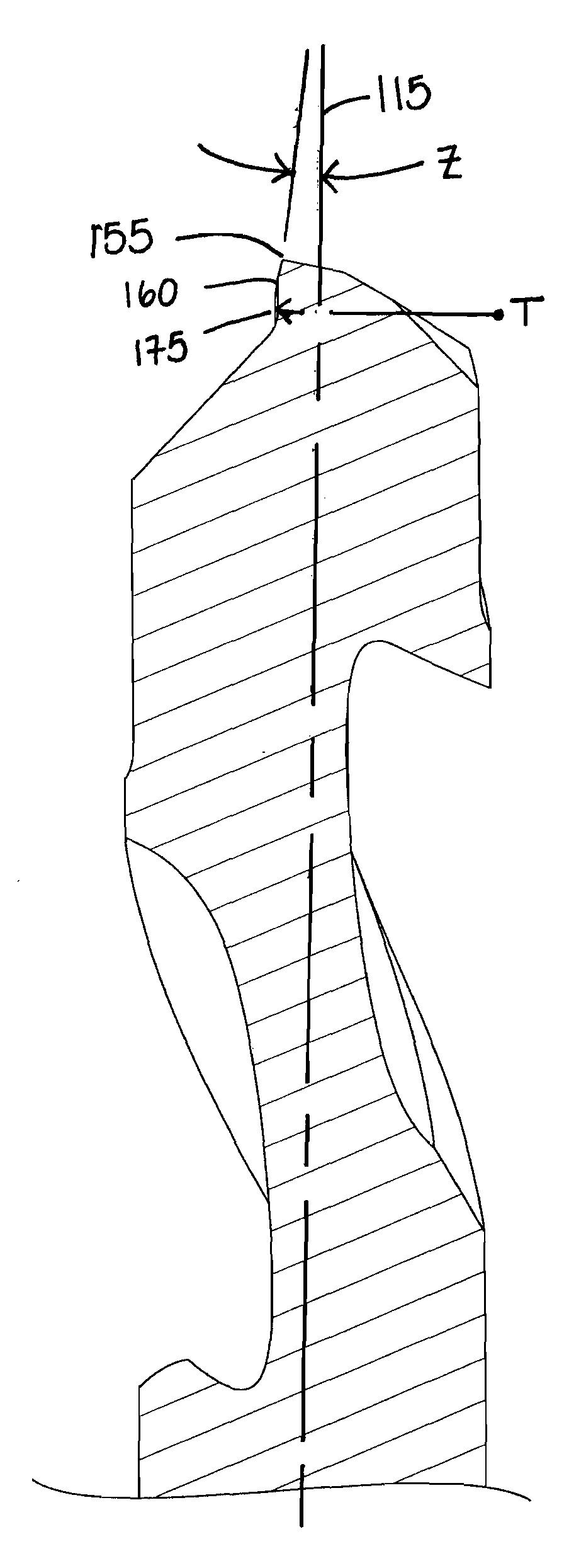
  • Twist Drill With Negative Axial Rake Transition Between The Lip And The Secondary Cutting Edge
  • Twist Drill With Negative Axial Rake Transition Between The Lip And The Secondary Cutting Edge
  • Twist Drill With Negative Axial Rake Transition Between The Lip And The Secondary Cutting Edge

Examples


Embodiment Construction

[0020]FIGS. 4 and 5 illustrate a perspective view of a drill in accordance with the subject invention while FIG. 6 illustrates an end view of that same drill.

[0021]In particular, FIGS. 4-6 illustrate a drill 105 for making a hole within a workpiece. The drill 105 has a body 110 extending along a longitudinal axis 115. At least one flute 120 extends along the body 110. However, the subject invention is applicable to drills with up to four flutes. Just as before, for clarity, only the cutting edges associated with one flute will be discussed with the understanding that the cutting edges associated with the opposing flute are symmetric. In particular, end segment 130 (FIG. 6) is defined by the area above line 129 and to the right of the first primary cutting edge 145, the secondary cutting edge 150 and the tertiary cutting edge 155. As can be seen, another end segment 130a exists above line 129 and to the left of the cutting edges but will not be discussed with the understanding that t...


PUM

PropertyMeasurementUnit
axial rake angleaaaaaaaaaa

Abstract

A drill for making a hole within a workpiece has a body extending along a longitudinal axis, at least one flute extending along the body, and a drill point extending from the end of the body. The drill point has a periphery and is comprised of a chisel edge, a primary cutting edge extending inwardly from the periphery, a secondary cutting edge extending outwardly from the chisel edge, and a tertiary cutting edge connecting the primary cutting edge with the secondary cutting edge, wherein the tertiary cutting edge has a negative axial rake angle. A method for producing such a drill point is also disclosed wherein in one grinding pass a gash forms the axial rake angle of the secondary cutting edge, and in a separate grinding pass a portion of the secondary cutting edge is removed to produce a tertiary cutting edge having an axial rake angle that is negative.

Description

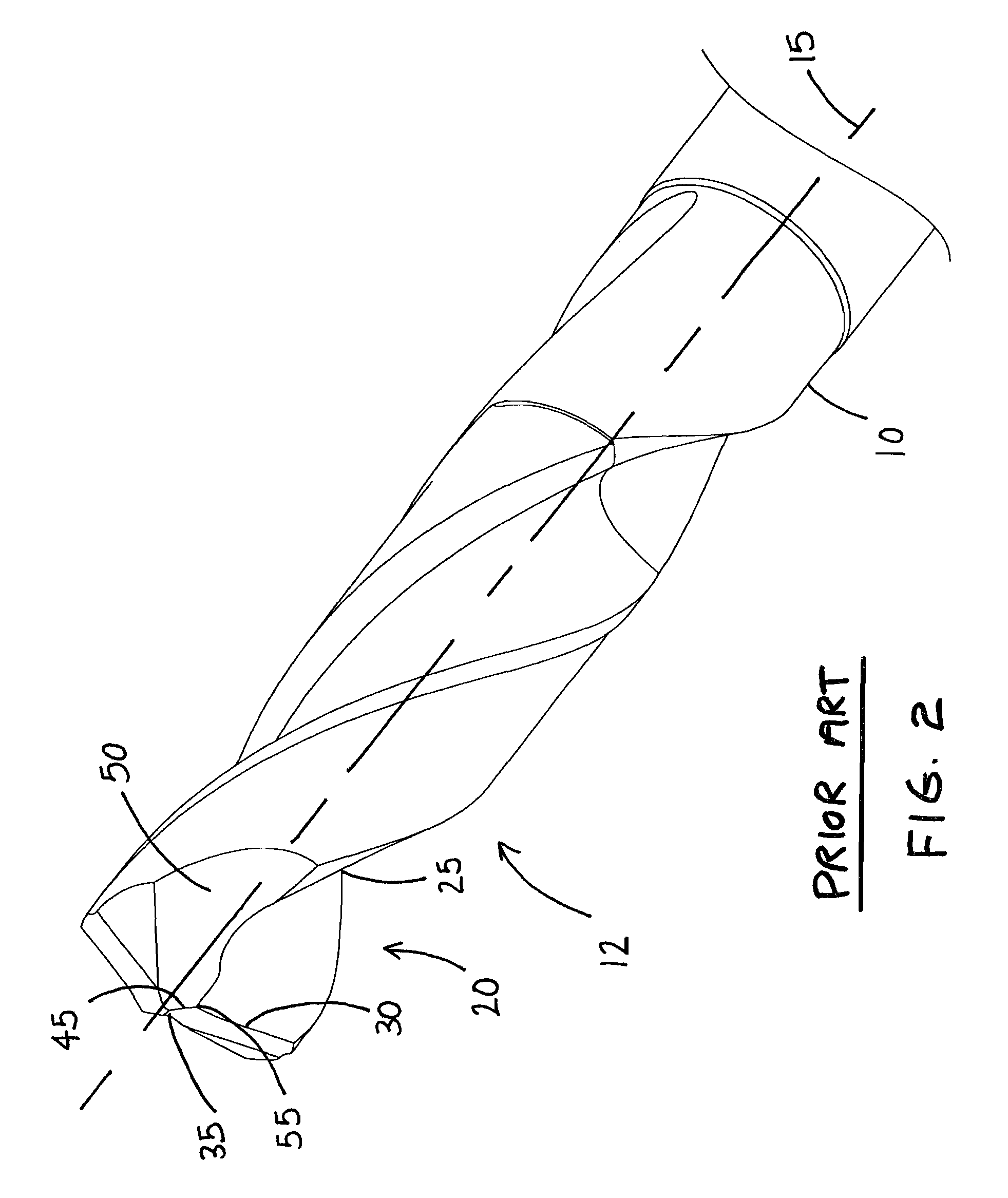
BACKGROUND OF THE INVENTION[0001]1. Field of the Invention[0002]The subject invention is directed to a twist drill and in particular to the transition between the primary cutting edge (lip) and the secondary cutting edge of the drill point of a twist drill.[0003]2. Description of Related Art[0004]Twist drills are typically fabricated through grinding operations utilizing a grinding wheel moved about a blank in a predetermined pattern to create the relatively complicated geometries found on such drills. In particular, major surfaces of the drill point result through the fabrication of the flute and an associated gash adjacent to the flute.[0005]Directing attention to FIGS. 1-3, a typical prior art drill 5 has a body 10 extending along a longitudinal axis 15 and a drill point 20 extending from the end 12 of the body 10. At least one flute 25, formed with a first grinding operation, extends along the body 10 and terminates at the drill point 20. The intersection of the flute 25 with th...

Claims


Application Information

Patent Timeline
Patent Type & Authority Applications(United States)
IPC IPC(8): B23B51/02B24B1/00
CPCB23B51/02B23B2251/04B23B2251/14B24B3/24Y10T408/9097Y10T408/909B23B51/00
Inventor GEORGE, STEPHEN MICHAEL
Owner KENNAMETAL INC
Learn More