Connecting block improved in crosstalk-characteristics

Inactive Publication Date: 2010-12-16
LG CABLE LTD (KR)
View PDF3 Cites 3 Cited by
  • Summary
  • Abstract
  • Description
  • Claims
  • Application Information

AI Technical Summary

Benefits of technology

[0017]The connecting block may further include an auxiliary coupling pin contacted with a terminal pin, other than the terminal pin contacted with the coupling pin, among terminal pins belonging to the same terminal pin pair and extending in a direction opposite to an extending direction of the coupling pin to reduce alien crosstalk.
[0022]According to the present invention, a capacitance value is not changed due to the structure in which a coupling pin is molded in a side cover, so it is possible to apply a constant amount of coupling to the connecting block.
[0023]In addition, the coupling pin is not integrated with the terminal pin, differently from the conventional art, and an electric contact between the coupling pin and the corresponding pin can be made only by coupling of the side cover, which ensures easy assembling and dissembling.

Problems solved by technology

However, in a conventional connecting block, crosstalk occurs between IDC terminal pins in the housing when a communication cable is connected thereto, and alien crosstalk occurs between IDC terminal pins of adjacent blocks, thereby causing loss of signal power.
However, the connecting system disclosed in U.S. Pat. No. 6,346,005 has a drawback in that an overall size of the block is seriously increased.
Also, the connecting block disclosed in U.S. Pat. No. 7,322,847 has a drawback in that the structure of IDC terminal pin should be changed, resulting in back compatibility with existing products.
In case of the IDC terminal assembly disclosed in U.S. Pat. No. 7,121,870, the extending conductor used for coupling is integrated with IDC, so an assembling work is not easy.
In addition, there is limit in that align crosstalk between blocks cannot be reduced.
In addition, the IDC terminal assembly disclosed in U.S. Pat. No. 7,121,870 has a problem in that a capacitance value between each extending conductor and IDC is seriously changed depending on an assembling tolerance, thereby not ensuring constant coupling.
However, if the assembling tolerance is too small, an assembling work becomes very difficult and parts should be prepared with very precise dimensions.

Method used


Image

  • Connecting block improved in crosstalk-characteristics
  • Connecting block improved in crosstalk-characteristics
  • Connecting block improved in crosstalk-characteristics

Examples


Embodiment Construction

[0032]Hereinafter, preferred embodiments of the present invention will be described in detail with reference to the accompanying drawings. Prior to the description, it should be understood that the terms used in the specification and the appended claims should not be construed as limited to general and dictionary meanings, but interpreted based on the meanings and concepts corresponding to technical aspects of the present invention on the basis of the principle that the inventor is allowed to define terms appropriately for the best explanation. Therefore, the description proposed herein is just a preferable example for the purpose of illustrations only, not intended to limit the scope of the invention, so it should be understood that other equivalents and modifications could be made thereto without departing from the spirit and scope of the invention.

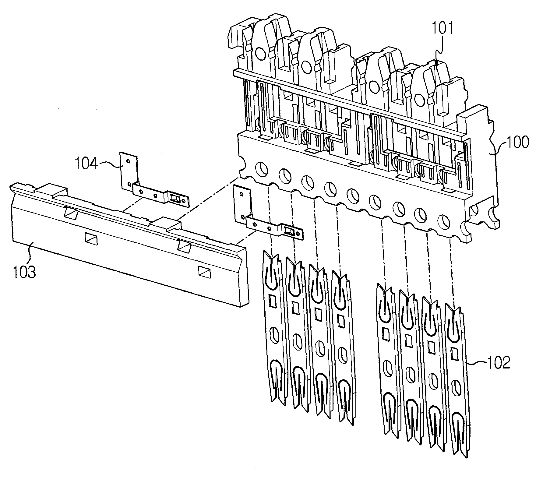
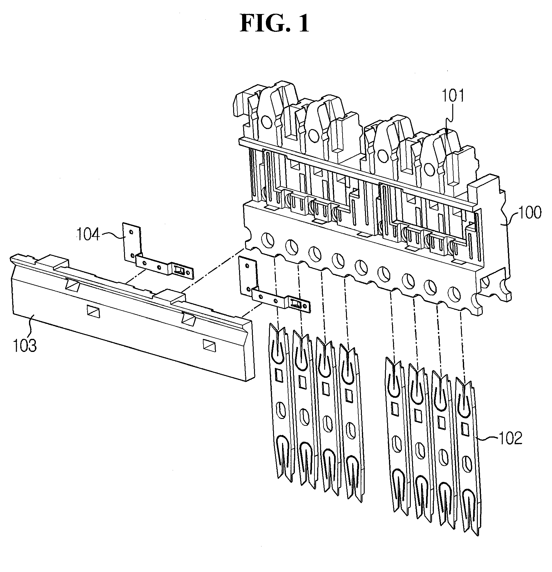
[0033]FIG. 1 is an exploded perspective view showing a connecting block according to one embodiment of the present invention.

[0034]Ref...


PUM


Abstract

A connecting block includes a housing having a plurality of slots extending from an upper surface thereof to an inside thereof with intervals, a plurality of terminal pins installed in the slots, a dielectric cover made of an insulating resin and coupled to the housing to cover a side of the housing, and a coupling pin electrically contacted with a terminal pin of any one pair among terminal pins belonging to different terminal pin pairs and extending opposite to a terminal pin of the other pair. The coupling pin is molded in a body of the dielectric cover such that the insulating resin is interposed between the coupling pin and the terminal pin opposite to the coupling pin.

Description

BACKGROUND OF THE INVENTIONCross-Reference to Related Application[0001]This application claims priority under 35 USC 119(a) to Korean Patent Application No 10-2009-0051894 filed in Republic of Korea on Jun. 11, 2009, the entire contents of which are incorporated herein by reference.FIELD OF THE INVENTION[0002]The present invention relates to a connecting block for connection of a communication cable, and more particularly to a connecting block having a coupling pin for reducing crosstalk between pairs of terminal pines or alien crosstalk between connecting blocks.DESCRIPTION OF THE RELATED ART[0003]Generally, a connecting block having a plurality slots for the insertion of conducive wires and a plurality of terminal pins corresponding thereto is installed in a communication terminal box for the purpose of wiring of communication cables such as UTP cable.[0004]A connecting block, known as ‘110 block’ in the art, includes an insulator housing and an IDC (Insulation Displacement Connec...

Claims


Application Information

Patent Timeline
IPC IPC(8): H01R4/24H01R24/00
CPCH01R4/242H01R9/24H01R13/6616H01R13/6477H01R13/6464Y10S439/941H01R13/6461H01R43/24H01R13/652
Inventor LEE, DONG-EUNBAECK, JONG-SEBCHO, YOUNG-ILKIM, SU-JONG
Owner LG CABLE LTD (KR)
Why Eureka
Try Eureka