
Telecommunications cabling system, and electrical connection module shielding interface therefor

Inactive Publication Date: 2015-01-01
COMMSCOPE TECH LLC
View PDF4 Cites 4 Cited by
  • Summary
  • Abstract
  • Description
  • Claims
  • Application Information

AI Technical Summary

Benefits of technology

The patent text describes how the outer shell of the device helps to reduce interference between wires that are connected to the device. This improves the overall performance of the device.

Problems solved by technology

In the field of telecommunications, wires used to carry the telecommunications signals are susceptible to noise from a variety of sources, including neighbouring wires in the same cable which may introduce near-end crosstalk (NEXT) or far-end crosstalk (FEXT), and nearby cables which may introduce alien crosstalk (AXT).
As data transmission rates increase, the effect of this noise on error rates also increases.

Method used


Image

  • Telecommunications cabling system, and electrical connection module shielding interface therefor
  • Telecommunications cabling system, and electrical connection module shielding interface therefor
  • Telecommunications cabling system, and electrical connection module shielding interface therefor

Examples


Embodiment Construction

[0056]Where the terms “front”, “rear”, “top”, “bottom”, “upper”, “lower” and the like are used below, it will be understood that these are used simply to describe the orientations of various components relative to each other, and are not intended to be construed in an absolute sense. Accordingly, the skilled person will understand that these terms should be interchanged appropriately when the orientation of the system (relative to a user, for example) is changed.

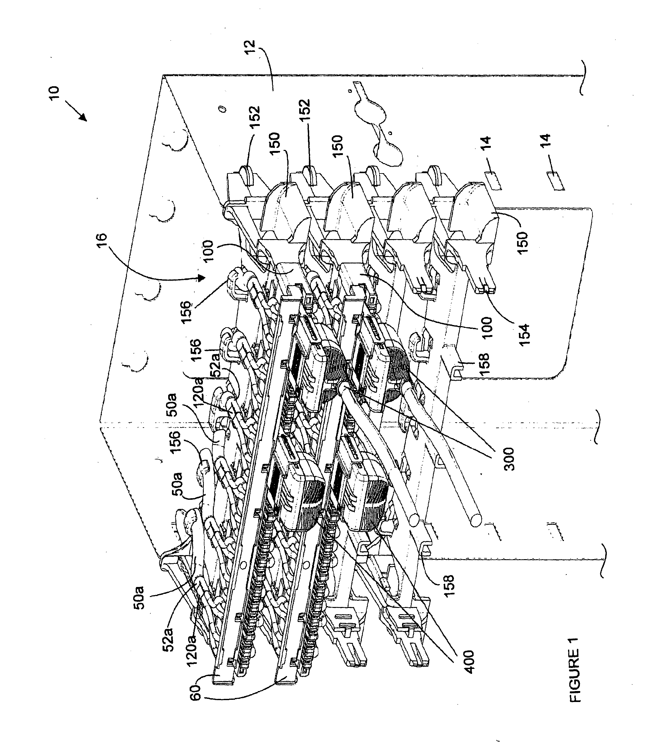
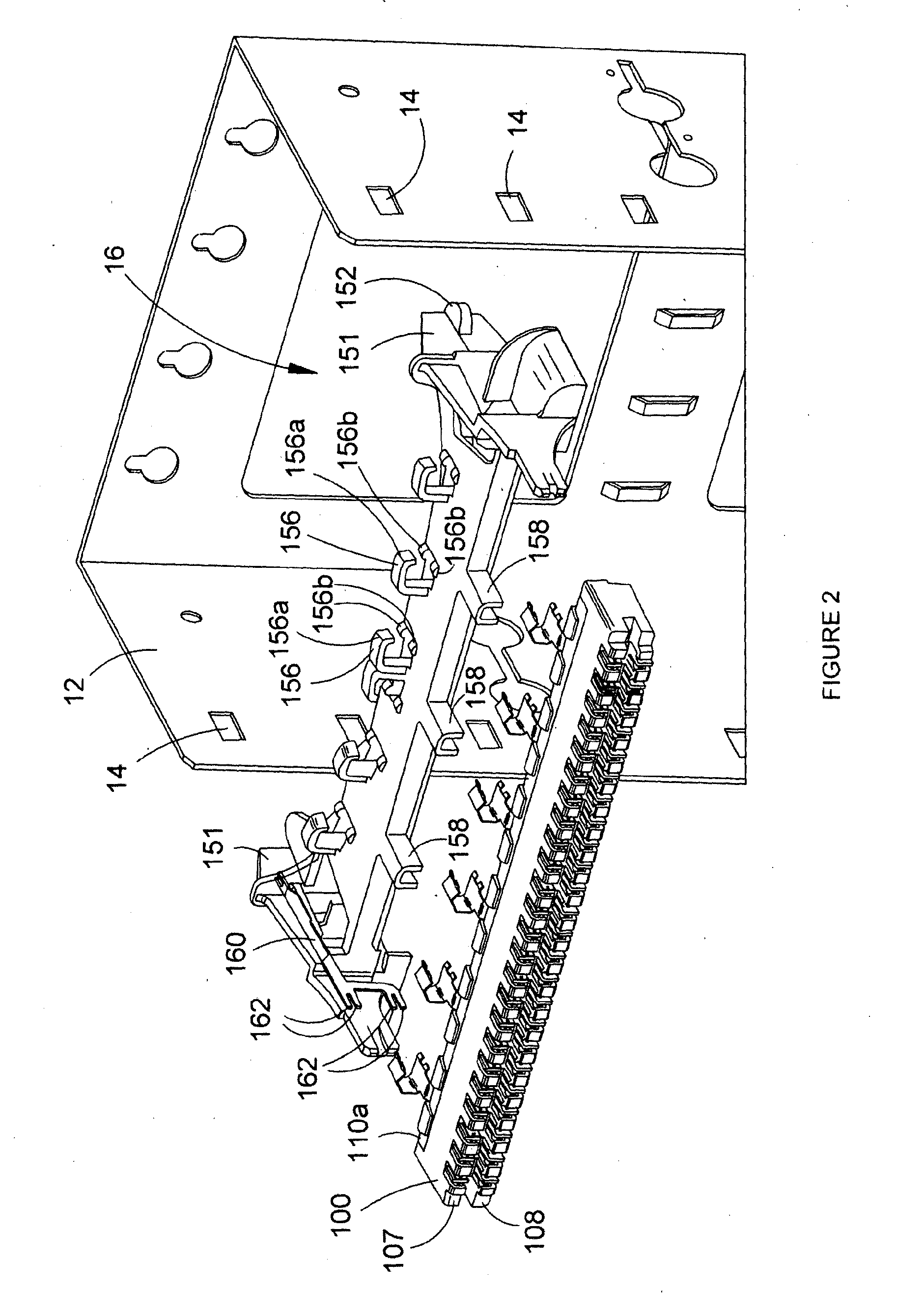
[0057]Referring to FIGS. 1 to 3, there is shown a patch-by-exception telecommunications cabling system 10 including an earthed (grounded) support (backmount frame) 12 to which connection modules 100 are mounted, via respective cable managers 150. In use, telecommunications cables 50a housed in backmount frame 12 can be fed through cable retention members 156 on respective top surfaces of the cable managers 150, and wires of the cables 50a terminated on the connection modules 100 (FIG. 4).

[0058]Backmount frame 12 can be earth...


PUM


Abstract

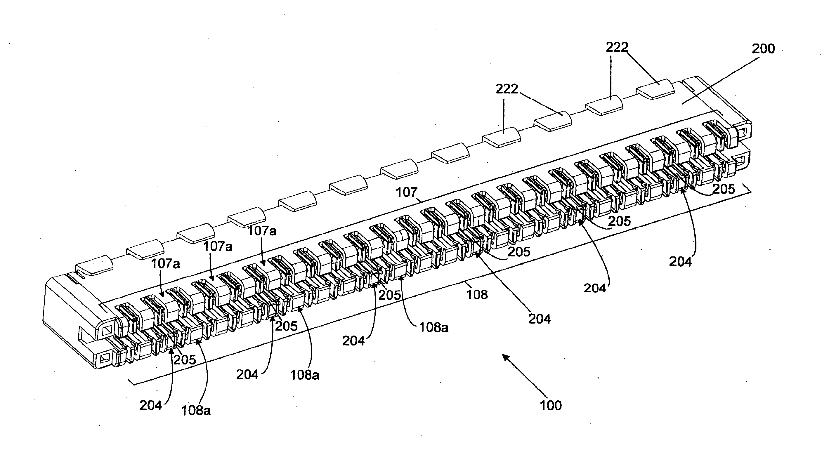
A telecommunications cabling system, including:(a) an earthed support (12); and(b) at least one connection module (100) mounted to the earthed support (12), including:(i) a housing (200; 220) for a plurality of electrical contact members (212), the housing (200; 220) having a plurality of recesses (202) to receive wires of at least one shielded cable (50);(ii) at least one opening to receive an end of an electrical connector (300; 400) to place electrical contacts at the end of the electrical connector (300; 400) in direct or indirect electrical communication with at least some of the wires; and(iii) a shielding interface (110) for the connection module (100);wherein the shielding interface (110) is simultaneously contactable with shielding (52) of the shielded cable (50), a corresponding shielding interface (500) of the electrical connector (400), and the earthed support (12).

Description

CROSS-REFERENCE TO RELATED APPLICATIONS[0001]The contents of Australian Patent Application No. 2011265514, entitled “Telecommunications cabling system”, Australian Patent Application No. 2011265515, entitled “Shielding interface for an electrical connection module”, and Australian Patent Application No. 2011265516, entitled “Electrical connection module”, are hereby incorporated by reference in their entireties.TECHNICAL FIELD[0002]The described embodiments relate to a telecommunications cabling system, to an electrical connection module, and to a shielding interface for an electrical connection module, for use in a telecommunications network.BACKGROUND[0003]In the field of telecommunications, wires used to carry the telecommunications signals are susceptible to noise from a variety of sources, including neighbouring wires in the same cable which may introduce near-end crosstalk (NEXT) or far-end crosstalk (FEXT), and nearby cables which may introduce alien crosstalk (AXT). As data ...

Claims


Application Information

Patent Timeline
IPC IPC(8): H01R13/659H01R13/6471
CPCH01R13/659H01R13/6471H01R4/2429H01R9/034H01R9/037H01R9/2416H01R9/2491H01R12/721H01R13/518H01R13/6463H01R13/6589H01R24/60H01R2201/04H04Q1/06H04Q1/13H01R13/65917H01R13/65914H01R13/6585H01R13/6599H01R2107/00H01R2201/16
Inventor ALLWOOD, BRENT DAVIDPUROHIT, KAVITANICHOLLS, BRYCE LINDSAYDENNES, WAYNE WILLIAMTRUSKETT, KEVIN JAMES
Owner COMMSCOPE TECH LLC
Learn More