
Interference Control, SINR Optimization and Signaling Enhancements to Improve the Performance of OTDOA Measurements

a technology of interference control and optimization, applied in the direction of instruments, high-level techniques, wireless commuication services, etc., can solve the problems of ineffective gps receiver, inability of gps receiver to receive signals from an appropriate quantity of gps satellites, and the need for wireless devices operating in such systems

Active Publication Date: 2010-12-16
GOOGLE TECH HLDG LLC
View PDF100 Cites 295 Cited by
  • Summary
  • Abstract
  • Description
  • Claims
  • Application Information

AI Technical Summary

Benefits of technology

[0017]The network, or LS, can further transmit relative eNB timing to allow the UE to perform autonomous fixes (UE-centric), but this also requires the network or LS to make available to the UE, or a secure entity in the UE, specific eNB locations, which the network operator may not wish to do.

Problems solved by technology

However, there are some circumstances under which the GPS receiver is ineffective.
For example, when a user and his or her cell phone are located within a building, the GPS receiver may not be able to receive signals from an appropriate quantity of GPS satellites to enable the location server to determine the device's position.
Additionally, wireless devices in private systems are not required to meet the FCC E-911 mandates and may not include a GPS receiver.
However, circumstances may arise under which determining locations of wireless devices operating in such systems may be necessary.
Studies seem to indicate that the existing common reference symbols are not adequate from a hearability perspective.
In such a case, it is no longer possible for the eNB to enable the UE to better hear all other eNBs by self-muting a single sub frame (though if the serving eNB has knowledge of when the neighboring eNBs are sending PRS sub frames, it is possible for the eNB to mute to allow the UE to hear PRS transmissions from selected neighbors).
Additionally, since the PRS sub frames on the non-serving eNBs are not synchronized to those of the serving eNB, the UE does not know where to look for the PRS sub frames, and it would then be necessary for the UE to continuously scan for PRS sequences.
In this case, the problem is actually more complex than SCH detection.
Thus, the set of neighboring eNBs (and the corresponding timing) discovered by the UE via RRM cell search are not sufficient to identify the eNBs which should be measured for location purposes.
Without some sort of assistance from the serving eNB, the detection of PRS is much more complex and difficult and computationally complex than detection of the SCH.
Note further, that blind detection of PRS sequences in a very large search space will perform quite poorly.
However, for a weak signal, the maximum of a large number of correlations in the absence of the desired signal will generally exceed correlation with the desired signal present, and thus, the timing estimate will be incorrect.
Furthermore, not all eNBs may use the same periodicity.
Alternately, for the asynchronous case, it might be that specially designed PRS transmissions may have no benefit over using CRS+serving cell muting.

Method used


Image

  • Interference Control, SINR Optimization and Signaling Enhancements to Improve the Performance of OTDOA Measurements
  • Interference Control, SINR Optimization and Signaling Enhancements to Improve the Performance of OTDOA Measurements
  • Interference Control, SINR Optimization and Signaling Enhancements to Improve the Performance of OTDOA Measurements

Examples


Embodiment Construction

[0026]Aside from enhancement of the basic reference signal sequence, the OTD waveform observability (i.e. SINR) using inter-cell (including inter-sector) coordination methods, such as COMP methods can also be optimized.

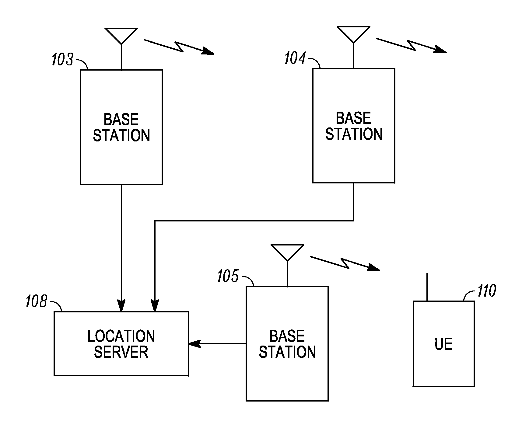
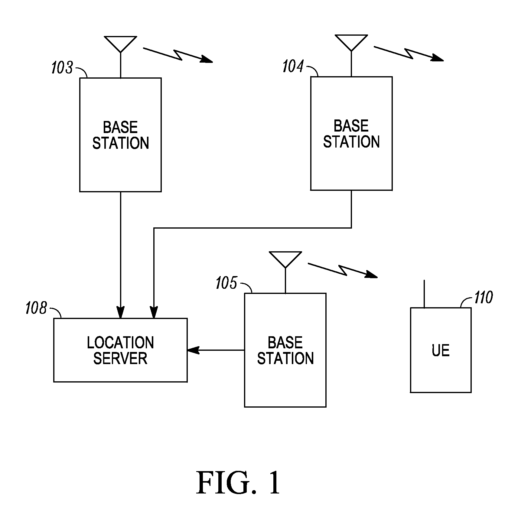
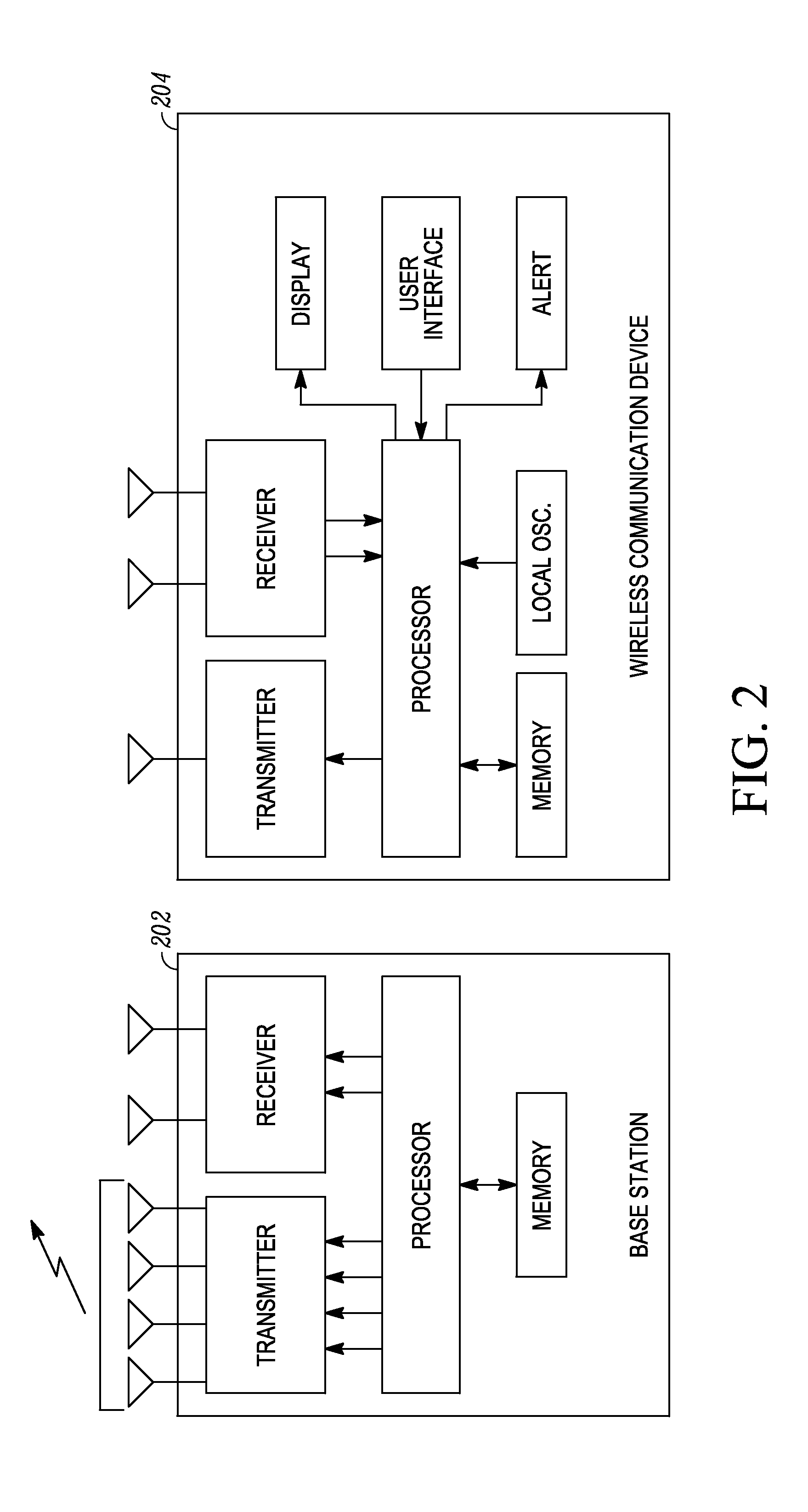
[0027]One embodiment disclosed herein includes a method of inter-cell, or inter-sector, enhanced observed time difference (OTD) signal transmission coordination. For example, a plurality of eNBs 103, 104, 105 (FIG. 1) transmitting enhanced OTD measurement signals may do so jointly—e.g. occupying the same, or related but jointly or co-scheduled time-frequency regions. If the identical time-frequency region is used, a single “virtual” eNB for the purposes of OTD measurements may be reported by the UE 110. Such a “virtual” eNB may employ an OTD measurement waveform, or sequence, distinct from that of the eNBs comprising the joint transmission. Such joint transmissions may preferentially be done using synchronous transmitters operating under the control of the same eNB—fo...


PUM


Abstract

A wireless terminal receives signaling information, pertaining to a reference signal transmission in at least one specifically designated sub frame, the signaling information including a list, the list including base station identities. The terminal determines, from at least one of the base station identities in the list, the time-frequency resources associated with a reference signal transmission intended for observed time difference of arrival (OTDOA) measurements from a transmitting base station associated with said one base station identity. The time of arrival of a transmission from the transmitting base station, relative to reference timing, is measured. The wireless terminal can receive a command from a serving cell to start performing inter-frequency OTDOA measurement on a frequency layer containing reference signals, the frequency layer distinct from the serving frequency layer, the serving frequency layer not containing positioning reference signals. The wireless terminal can perform OTDOA measurements subsequent to the reception of the command on a carrier frequency different from the serving cell carrier frequency. A base station transmitter can jointly schedule a reference signal transmission from a plurality of base station transmitters for the purpose of OTD estimation enhancement, and transmit identical reference signals from the plurality of base station transmitters, the reference signals being identical both in the signal sequence and time-frequency resources used for transmission.

Description

FIELD OF THE DISCLOSURE[0001]The present disclosure relates to interference control, signal quality optimization and signaling enhancements to improve the performance of observed time difference of arrival (OTDOA) measurements in wireless receivers for the purpose of assisting user position estimation in wireless networks.BACKGROUND[0002]Wireless communication networks are well known. Some networks are completely proprietary, while others are subject to one or more standards to allow various vendors to manufacture equipment, such as wireless terminals, for a common system. One such standards-based network is the Universal Mobile Telecommunications System (UMTS). UMTS is standardized by the Third Generation Partnership Project (3GPP), collaboration between groups of telecommunications associations to make a globally applicable third generation (3G) mobile phone system specification within the scope of the International Mobile Telecommunications-2000 project of the International Telec...

Claims


Application Information

Patent Timeline
IPC IPC(8): H04W4/00
CPCG01S1/30G01S5/0236G01S5/10H04W64/00H04L5/0094H04L27/2656H04L5/005Y02D30/00H04L27/2603G01S5/14H04W4/00H04L43/0852H04W24/10H04W72/044
Inventor KRISHNAMURTHY, SANDEEP H.LOVE, ROBERT T.NIMBALKER, ALJITSTEWART, KENNETH A.ZHUANG, XIANGYANG
Owner GOOGLE TECH HLDG LLC
Learn More