Tracking of emergency personnel

a technology for emergency personnel and tracking, applied in direction finders, direction finders using radio waves, instruments, etc., can solve the problems of multiple false readings on increased amplitude (false directions), and many false high amplitude paths to the targ

Active Publication Date: 2010-12-23
BAE SYST INFORMATION & ELECTRONICS SYST INTERGRATION INC
View PDF22 Cites 15 Cited by
  • Summary
  • Abstract
  • Description
  • Claims
  • Application Information

AI Technical Summary

Benefits of technology

[0006]One embodiment of the present invention provides a method for tracking personnel at a scene. The method includes measuring one or more response signal parameters for each of Y antenna patterns, thereby providing a Y sample array of response data from a target wireless emitter of a person to be tracked (such as a personal cell phone or a dedicated wireless emitter specifically used for tracking), wherein Y is greater than 1 (e.g., Y=64 or 4096; any number of antenna patterns can be used). The method further includes correlating the sample array to a plurality of entries in a database of calibrated arrays having known azimuths, to determine a line of bearing (LOB) to the target wireless emitter. The method further includes repeating the transmitting, measuring and correlating to determine one or more additional LOBs to the target wireless emitter, each LOB computed from a different geographic location, and geolocating the target wireless emitter based on the LOBs, thereby geolocating the person. The method may further include the preliminary steps of surveying an area of interest to identify wireless emitters within that area (e.g., using established discovery protocols), and selecting a target emitter discovered during the survey. This selection may be, for example, based on user input, or done automatically based on some established selection scheme. In one particular case, the target emitter is associated with a media access control (MAC) address and communication channel that is learned during the survey. Here, the method may further include transmitting a stimulus signal to the target emitter using the MAC address and communication channel. In another particular case, the correlating step includes generating a correlation plot having a peak using correlation factors resulting from correlation of the sample array to the plurality of entries in the database, identifying a target azimuth of the sample array based on the peak of the correlation plot, and determining the LOB to the target wireless emitter based on the target azimuth. In some cases, each of the LOBs is associated with position and heading tags provided by a global positioning satellite (GPS) module to assist in geolocating the target wireless emitter. The method may include graphically displaying geolocations of the target wireless emitter. The method may include periodically repeating the geolocating of the target wireless emitter, thereby periodically geolocating the person as that person moves around the scene. The one or more response signal parameters may include, for example, response signal amplitude. The method can be carried out, for example, using portable devices (e.g., vehicle-based, suitcase-based, and / or handheld devices) configured for performing the transmitting, measuring and correlating steps, and a command workstation (e.g., vehicle-based, suitcase-based, and / or handheld devices) wirelessly coupled to the portable devices is configured for performing the geolocating step.

Problems solved by technology

There are a number of problems associated with such amplitude-based techniques for locating 802.11 emitters.
For instance, the techniques tend to be highly inaccurate due to the incidence of RF multipath created by the RF waveforms emanating from the 802.11 emitters.
These waveforms bounce off conductive objects or surfaces in the environment, which causes multiple false readings on increased amplitude (false directions) that then disappear as the user leaves the multipath.
Thus, conventional amplitude-based locationing techniques will create many false high amplitude paths to the target that will be incorrect, and will not work in a high multipath environment, such as a neighborhood (e.g., street scene) or building (e.g., home, office building, or café).

Method used


Image

  • Tracking of emergency personnel
  • Tracking of emergency personnel
  • Tracking of emergency personnel

Examples


Embodiment Construction

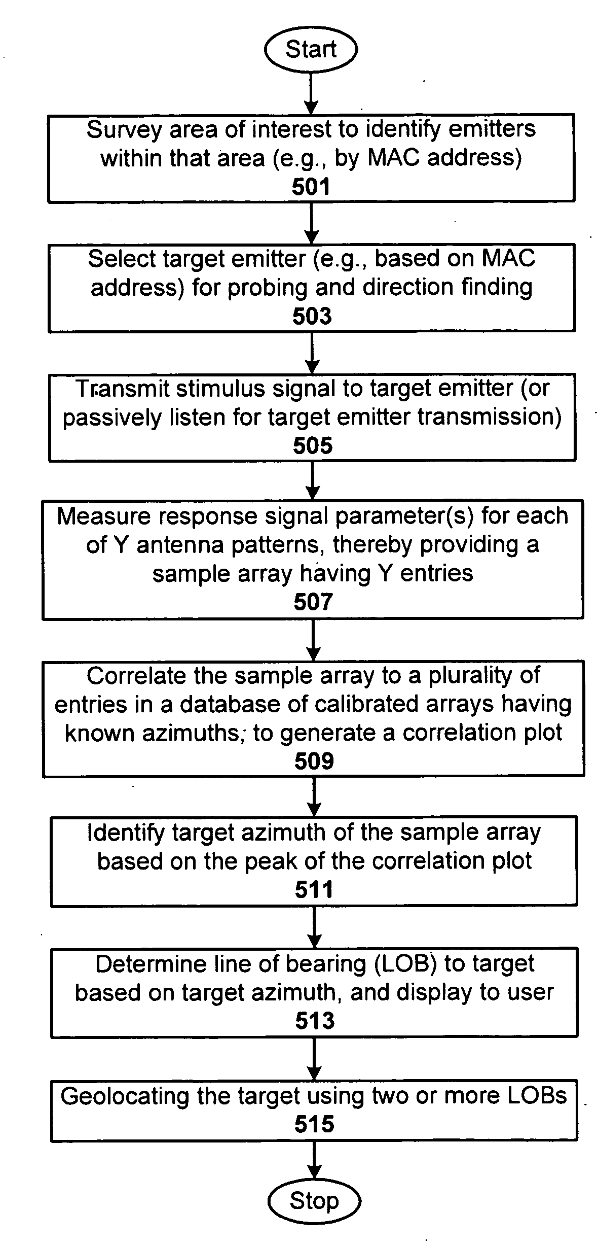
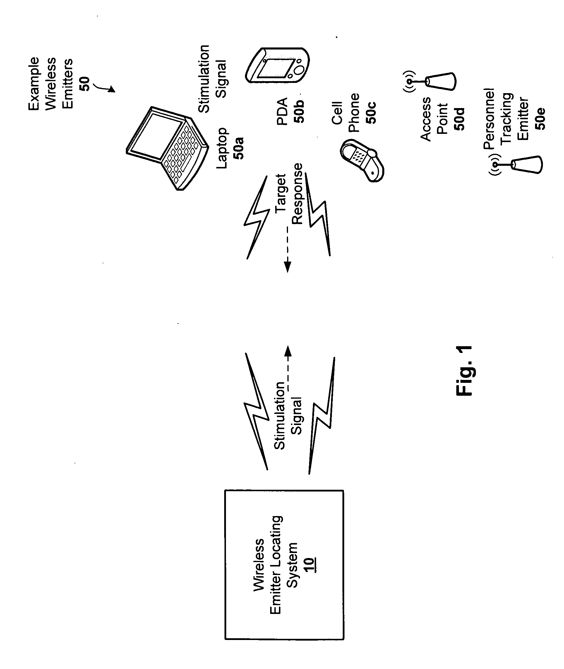
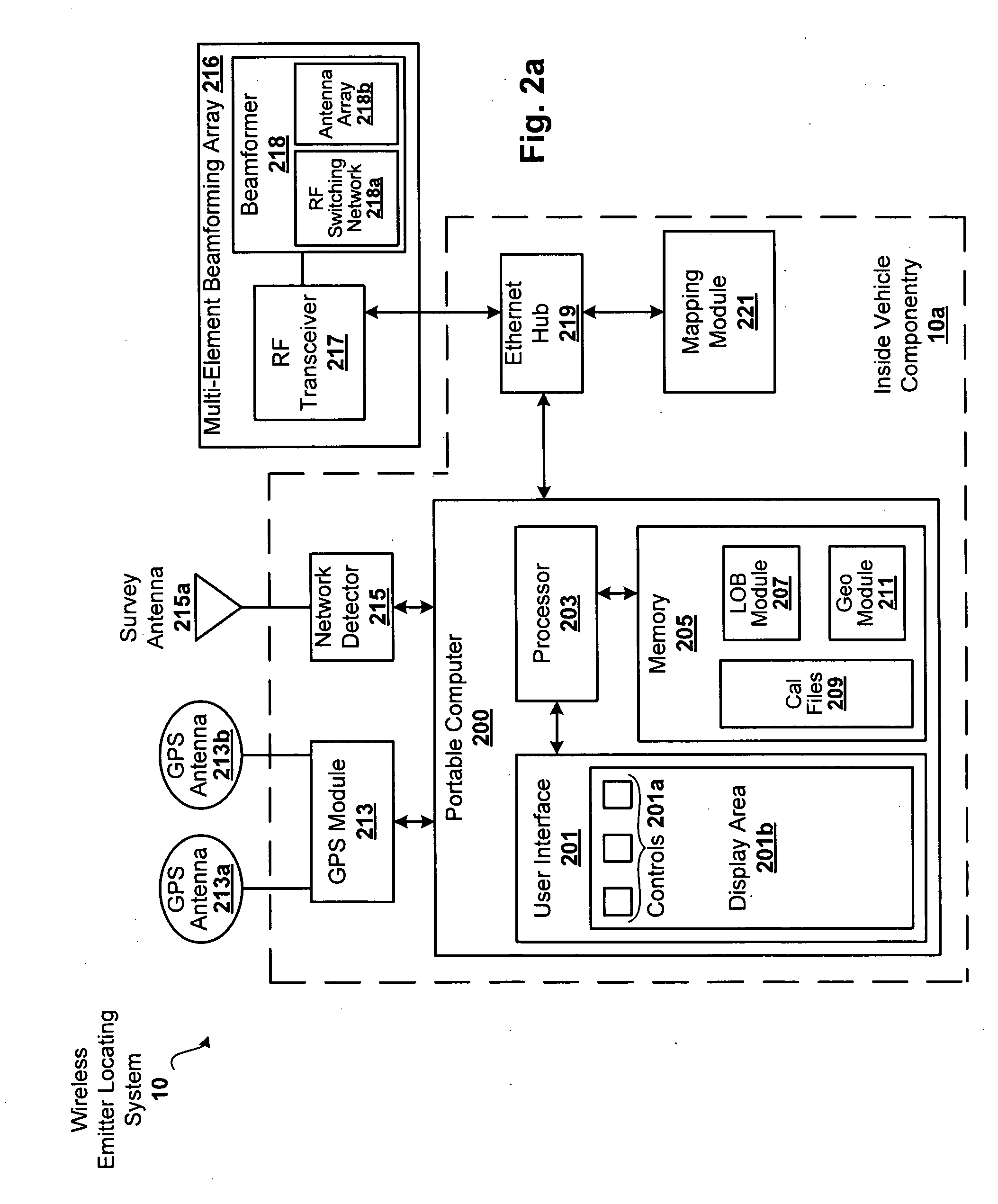
[0019]Techniques are disclosed that allow for the detection, identification, direction finding, and geolocation of emergency personnel in a given multipath environment. For example, the techniques can be used to detect and identify multiple lines of bearing (LOBs) to an IEEE 802.11 emitter attached to or otherwise possessed by the emergency responder that is inside a building or otherwise contained area not easily viewable from the outside. The LOBs from multiple vantage points can be used to geolocate and / or otherwise track the emergency responder. For instance, by integrating two or more of direction finding devices as described herein via wireless network, and locating those devices on respective emergency response vehicles placed around an incident scene, the individual LOBs can effectively be fused together to calculate a 3D geolocation (the geospacial intersection of 3 or more LOBs) of an IEEE 802.11 emitter carried by an emergency responder inside a building. The resulting ge...


PUM


Abstract

Techniques are disclosed that allow for the detection, identification, direction finding, and geolocation of emergency personnel in a given multipath environment. For example, the techniques can be used to detect and identify multiple lines of bearing (LOBs) to an IEEE 802.11 emitter of an emergency responder that is inside a building or otherwise hidden from view. LOBs from multiple vantage points can be used to geolocate and/or track the emergency responder. The resulting geolocation can be plotted on a map display or model of the scene (e.g., building, etc) so the precise position of the emergency responder having the targeted wireless emitter can be known.

Description

RELATED APPLICATIONS[0001]This application is related to U.S. application Ser. No. ______ (Attorney Docket BAEP-1122), filed Jun. 18, 2009, and titled “Direction Finding of Wireless Devices.” This application is also related to U.S. application Ser. No. ______ (Attorney Docket BAEP-1123), filed Jun. 18, 2009, and titled “Direction Finding and Geolocation of Wireless Devices.” Each of these applications is herein incorporated by reference in its entirety.FIELD OF THE INVENTION[0002]The invention relates to wireless communications, and more particularly, to techniques for direction finding and geolocating emergency personnel equipped with wireless devices such as those configured with IEEE 802.11 emitters and other such detectable emitters.BACKGROUND OF THE INVENTION[0003]Conventional techniques for locating IEEE 802.11 emitters (e.g., access points as well as laptops with IEEE 802.11 capability and other such clients) are based on measuring the amplitude of the 802.11 emitter with a ...

Claims


Application Information

Patent Timeline
Patent Type & Authority Applications(United States)
IPC IPC(8): G01S3/02
CPCG01S3/023G01S5/04G01S5/0072
Inventor KELLY, JOHN J.
Owner BAE SYST INFORMATION & ELECTRONICS SYST INTERGRATION INC
Why Eureka
Try Eureka