Multifocal ophthalmic lens

a multi-focal, ophthalmic technology, applied in the field of multi-focal ophthalmic lenses, can solve the problem of not being able to see an object at far distance without eyeglasses, and achieve the effects of reducing the possibility of halo and glare symptoms, reducing the possibility of image jump, and improving the comfort of far vision and near vision

Active Publication Date: 2010-12-23
HOYA CORP
View PDF6 Cites 42 Cited by
  • Summary
  • Abstract
  • Description
  • Claims
  • Application Information

AI Technical Summary

Benefits of technology

[0056]According to the present invention, a power distribution is set to vary progressively in an entire region of a far zone and a near zone in radial direction. Therefore, the depth of focus of far vision provided by the far zone and the depth of focus of near vision provided by the near zone can be deepened. As a result, clearly seen ranges of the far vision and near vision can be extended, therefore comfort of far vision and near vision can be improved.
[0057]In addition, according to the present invention, the possibilities of halo and glare symptoms can be reduced, and the possibility of image jump can be minimized.

Problems solved by technology

Accordingly, the quantity of light coming from the center zone that is used for night vision becomes insufficient, resulting almost impossible for a patient to see an object at far distance without eyeglasses.

Method used


Image

  • Multifocal ophthalmic lens
  • Multifocal ophthalmic lens
  • Multifocal ophthalmic lens

Examples


first embodiment (fig.1 to fig.9)

[A] First Embodiment (FIG. 1 to FIG. 9)

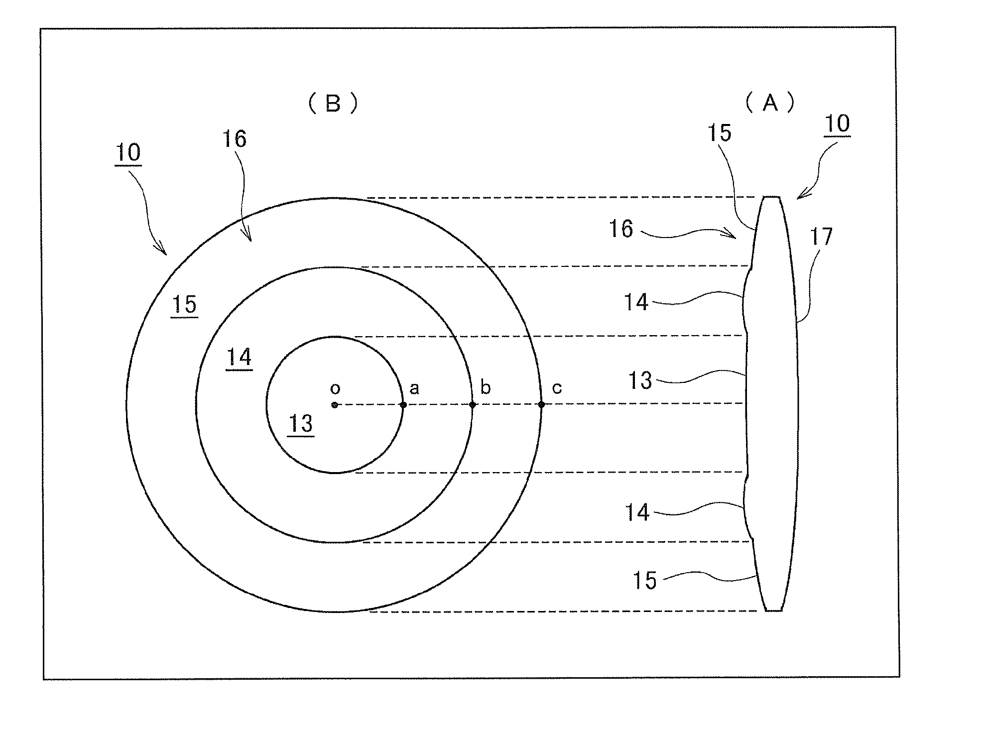
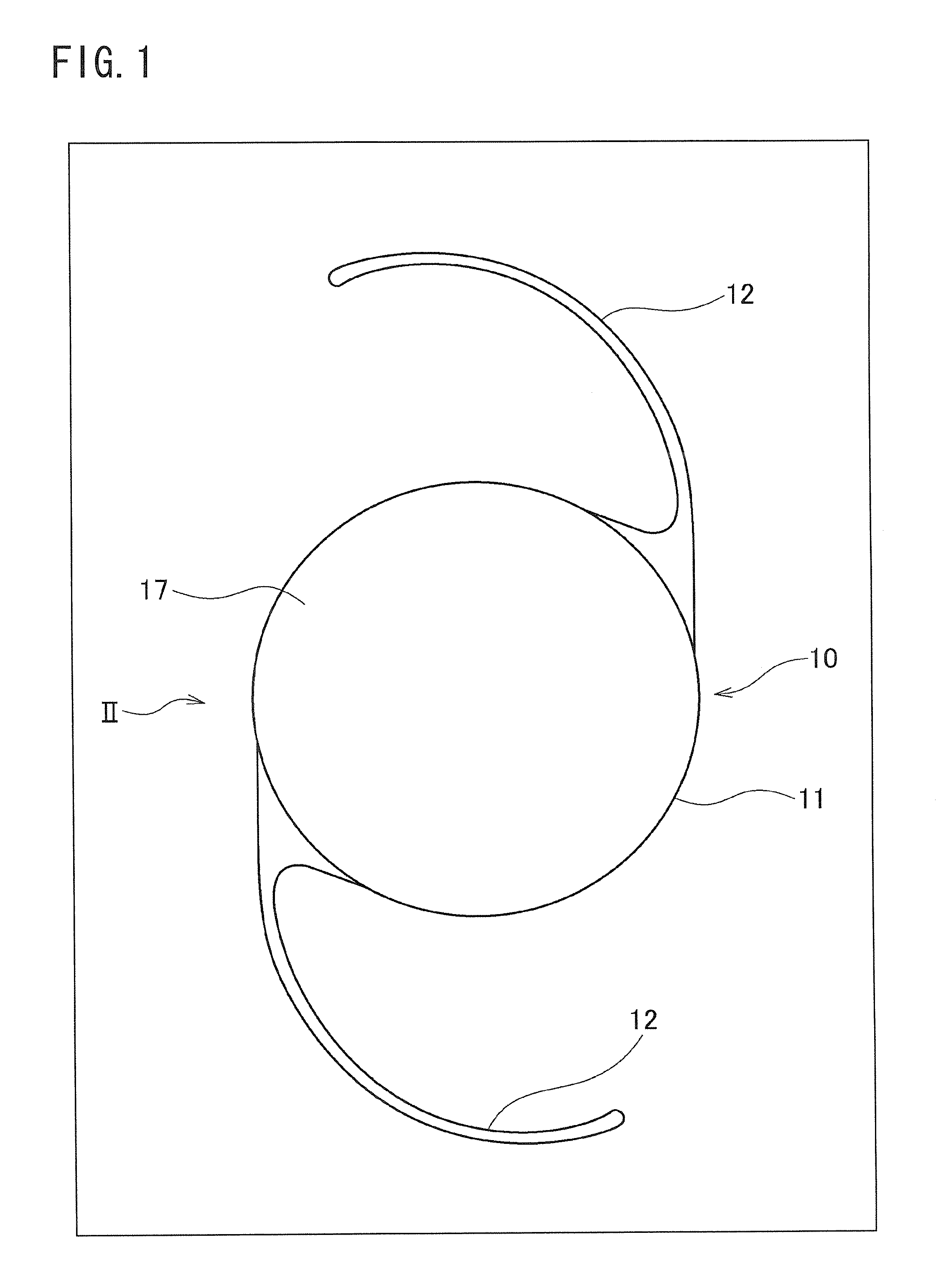
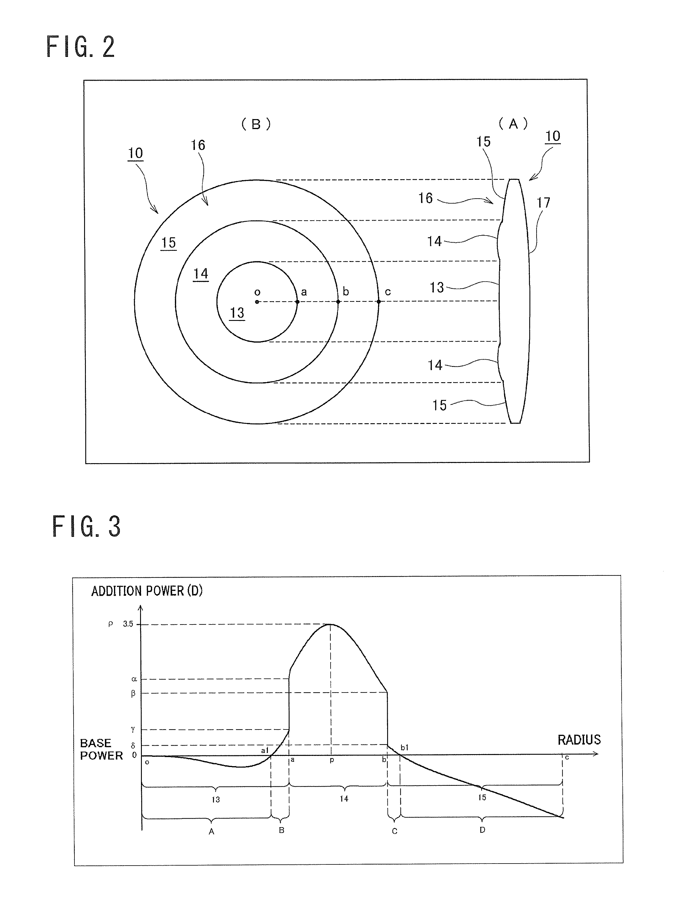
[0058]FIG. 1 is a front view illustration of an intraocular lens, being a first embodiment of an ophthalmic lens according to the present invention, and FIG. 2 is an illustration of a lens body 11 of the intraocular lens, being the first embodiment of the ophthalmic lens according to the present invention, wherein FIG. 2(A) is a side view of the lens body 11 of the intraocular lens shown in FIG. 1, and FIG. 2(B) is a front view of the lens body 11 of the intraocular lens in FIG. 1. FIG. 3 is a graph showing a power distribution in radial direction of the lens of the lens body 11 of the intraocular lens shown in FIG. 1 and FIG. 2. FIG. 4 is an illustration of a comparison of a depth of focus of the intraocular lens according to the first embodiment shown in FIG. 1 and FIG. 2, and the depth of focus of the intraocular lens according to the conventional art, wherein FIG. 4(A) illustrates a case of the intraocular lens according to the conventional...

second embodiment (fig.10)

[B] Second Embodiment (FIG. 10)

[0177]FIG. 10 is an illustration of lens body 31 of an intraocular lens of the second embodiment, an ophthalmic lens according to the present invention, wherein FIG. 10(A) is a front view, and FIG. 10(B) is a graph showing the power distribution in radial direction of the lens.

[0178]The intraocular lens 30 of the second embodiment includes a lens body 31 and support members that are not shown, and near zone 32 is arranged in the center zone of an optical region of the lens body 31, and an annular far zone 33 is arranged concentrically outside the region of the near zone 32.

[0179]The near zone 32 is a region for correcting the near vision, and the far zone 33 is a region for correcting the far vision. In addition, in these near zone 32 and the far zone 33, the power distribution in the entire region in radial direction (the near zone 32 is arranged in a range from point 0 to point d, and the far zone 33 is arranged in a range from point d to point e sho...


PUM


Abstract

A multifocal ophthalmic lens, including: a far zone for correcting a far vision; and a near zone for correcting a near vision, arranged concentrically in an optical region of the lens, wherein a power distribution is set to vary progressively in radial direction of the far zone and the near zone; power is altered discontinuously to have a stepwise power difference at a boundary between the far zone and the near zone, the value of the power difference at the boundary between the far zone and the near zone is not greater than a maximum value of an intermediate power for correcting an intermediate vision.

Description

TECHNICAL FIELD [0001]The present invention relates to a multifocal ophthalmic lens, particularly to a multifocal intraocular lens as one example, improved in correcting visual acuity of presbyopic eye.DESCRIPTION OF RELATED ART [0002]The multifocal ophthalmic lens has a depth of focus deeper than the monofocal ophthalmic lens. This characteristic of the multifocal ophthalmic lens is useful for correcting a presbyopic eye. Generally, a presbyopic eye with a monofocal intraocular lens can clearly see only an image of an object at a far distance and an object located between far distance and intermediate distance, or only an image of an object at a near distance and an object located between near distance and intermediate distance. For example, an eye with a monofocal intraocular lens having refractive power for correcting far vision in which refractive error is about 0 diopter (D), cannot clearly see an object at near distance. Therefore, in this case, an eyeglass is separately requi...

Claims


Application Information

Patent Timeline
Patent Type & Authority Applications(United States)
IPC IPC(8): G02C7/06G02C7/10A61F2/16
CPCA61F2/1618G02C7/044G02C7/042G02C7/028
Inventor SANGER, DEMAS
Owner HOYA CORP
Why Eureka
Try Eureka