Relief valve for discharging a dielectric gas between two volumes of a high-voltage or medium-voltage interrupting chamber

a dielectric gas and relief valve technology, which is applied in the direction of mechanical equipment, functional valve types, transportation and packaging, etc., can solve the problems of circuit-breaker fitted with it being exposed, not necessarily providing a seal, and losing its flexibility

Inactive Publication Date: 2010-12-30
ALSTOM TECH LTD
View PDF7 Cites 21 Cited by
  • Summary
  • Abstract
  • Description
  • Claims
  • Application Information

AI Technical Summary

Benefits of technology

[0027]To this end, the invention provides a relief valve for discharging a dielectric gas between two volumes of a high-voltage or medium-voltage interrupting chamber, the valve comprising a body including at least one open passage with one end that defines a closure member seat, at least one stop member attached to the body and, as a closure member, at least one flexible metal blade interleaved between the closure member seat and the stop member and having one end that is secured to the body, the metal of the blade being adapted to withstand high temperatures up to T1≈2500° C., the fle...

Problems solved by technology

Its major drawback is losing its flexibility if the circuit-breaker fitted with it is exposed to low temperatures.
At low temperatures that kind of elastomer closure member does not necessarily provide a seal, which is an operational hazard.
Its major drawbacks are its relatively high weight and the fact that it induces a high head loss because, when open, it partially obstructs the flow section for insulative gas.
A high head loss is detrimental ...

Method used


Image

  • Relief valve for discharging a dielectric gas between two volumes of a high-voltage or medium-voltage interrupting chamber
  • Relief valve for discharging a dielectric gas between two volumes of a high-voltage or medium-voltage interrupting chamber
  • Relief valve for discharging a dielectric gas between two volumes of a high-voltage or medium-voltage interrupting chamber

Examples


Embodiment Construction

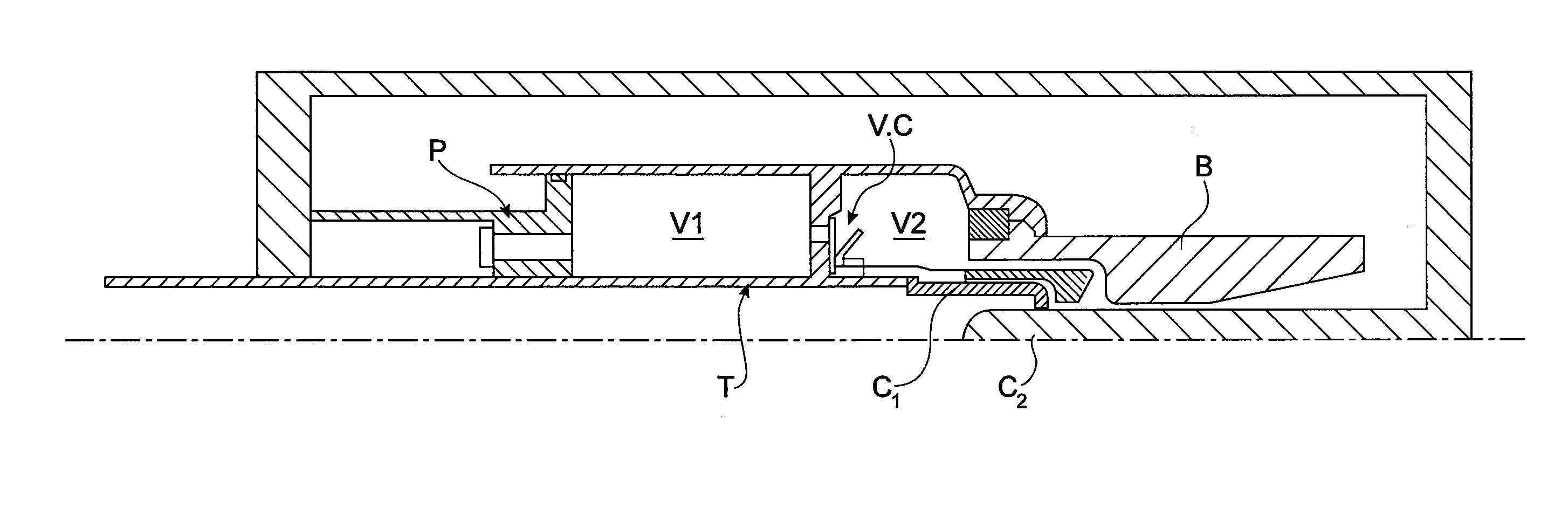
[0058]The relief valve of the invention includes a body 1 of cylindrical section that separates a first gas volume V1 from a second gas volume V2 in a high-voltage or medium-voltage interrupting chamber.

[0059]To be more precise, the body 1 includes a central bore 10 to be fitted over and fastened around a hollow operating tube T fastened to the mobile arc contact C1 of the chamber, as shown in FIG. 1. The relief valve V.C of the invention is for discharging dielectric gas from the volume V1 to the volume V2 if the action of the operating tube T via the stationary blower piston P causes the pressure to rise in the volume V1. In the chamber represented in FIG. 9, the other contact C2 is fastened.

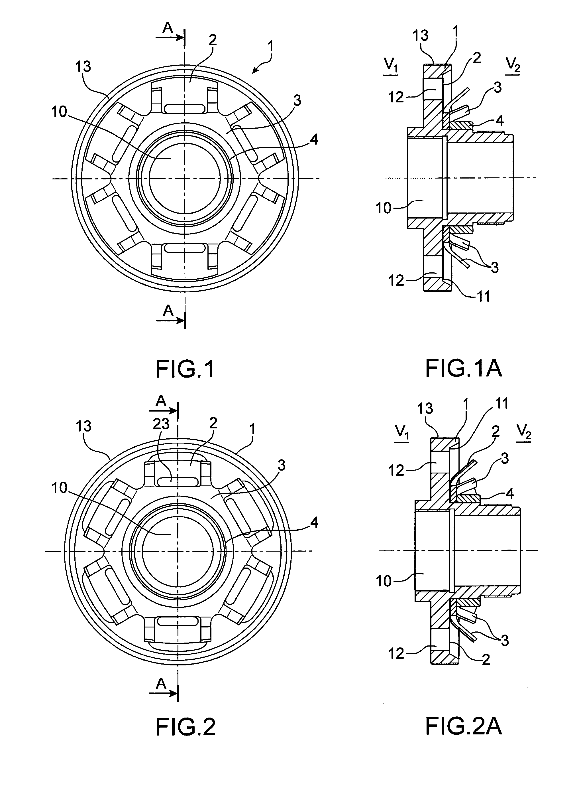
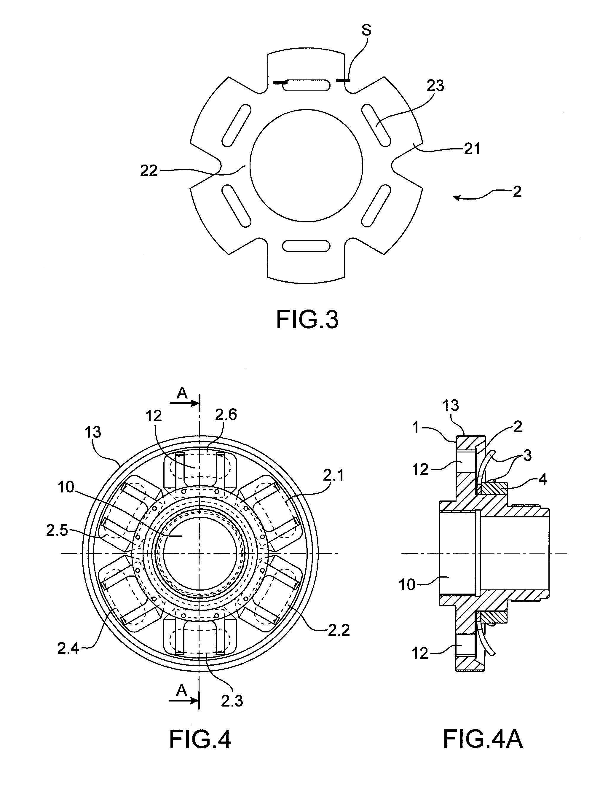
[0060]The closure member of the valve consists of a flexible metal blade 2 that is disposed between the closure member seat 11 and a stop member 3.

[0061]The closure member seat 11 is defined at the end of the open passage 12 formed in the valve body 1 and through which gas flows from the volum...


PUM


Abstract

A relief valve for discharging a dielectric gas between two volumes (V1, V2) of a high-voltage or medium-voltage interrupting chamber. There is used as a closure member a flexible metal blade secured to the body, the closure member therefore being opened by deformation of the flexible blade from a closed position (FIG. 1) in which it is pressed against a closure member seat formed in the body to a fully open position in which it fits closely against a stop member secured to the valve body whilst remaining within its elastic limit, the open passage for the gas being open in this fully open position (FIG. 1A) and the return of the blade from its fully open position to its closed position being possible because of its flexibility.

Description

CROSS REFERENCE TO RELATED APPLICATIONS OR PRIORITY CLAIM[0001]This application claims priority of French Patent Application No. 09 54419, filed Jun. 29, 2009.DESCRIPTION[0002]1. Technical Field[0003]The invention relates to a relief valve.[0004]The invention applies in particular to a high-voltage or medium-voltage interrupting chamber in which a dielectric gas is to be discharged via a valve.[0005]2. Prior Art[0006]In the field of high-voltage or medium-voltage circuit-breakers, relief valves are widely used to discharge dielectric gas between different volumes of the same chamber when breaking currents.[0007]Numerous patent applications may be mentioned, such as the applicant's application EP 2 045 827, describing the operation of a plurality of relief valves for a double compression volume chamber.[0008]One of the valves 122 described is a unidirectional valve incorporated in an operating tube 108 and its function is to open only if the pressure in the second compression chamber...

Claims


Application Information

Patent Timeline
IPC IPC(8): H01H33/04F16K15/00
CPCH01H33/905H01H2033/908H01H33/91Y10T137/7837
Inventor GREGOIRE, CYRILLEDRU, ROGERGRIESHABER, WOLFGANG
Owner ALSTOM TECH LTD
Why Eureka
Try Eureka