

Component, display part structure and portable terminal device
- Summary
- Abstract
- Description
- Claims
- Application Information
AI Technical Summary
Benefits of technology
Problems solved by technology
Method used
Image

Examples
exemplary embodiment 1
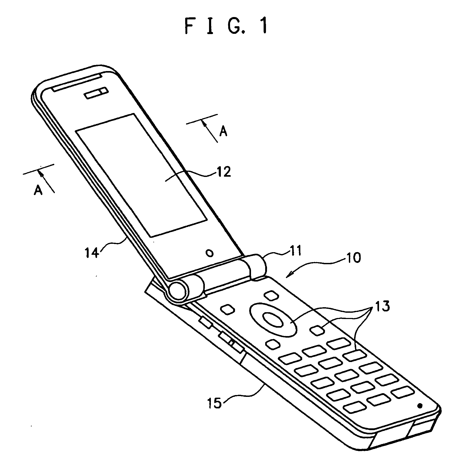
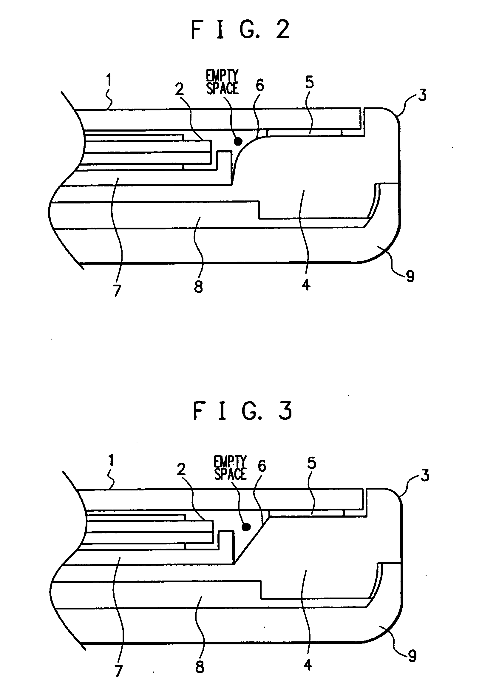
[0015]FIG. 2 is a side cross-sectional view of a display part structure of the folding cellular phone 10 of FIG. 1, in which a cross-section of the upper housing 14 taken on line A-A of FIG. 1 is partly illustrated.
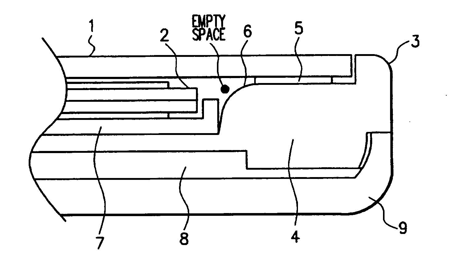
[0016]As illustrated in FIG. 2, the display part structure of an exemplary embodiment 1 includes a protecting member (a transparent panel) 1, a liquid crystal (a display panel) 2, a lighting unit (a lighting means) 7 and an upper casing (a component) 3. The protecting member (the transparent panel) 1 is made of a transparent resin material or the like, and protects the liquid crystal 2 from external impact, dust or the like. The liquid crystal 2 displays various information of characters and images. The lighting unit 7 irradiates the liquid crystal 2 from the rear face thereof. The lighting unit 7, the liquid crystal 2 and the protecting member 1 are successively incorporated in the upper casing 3. It is noted that the protecting member 1 corresponds to the display part 1...
exemplary embodiment 2
[0021]FIG. 3 is a side cross-sectional view of a display part structure of the folding cellular phone 10 illustrated in FIG. 1, in which a cross-section of the upper housing 14 taken on line A-A of FIG. 1 is partly illustrated. Since elements 1 through 9 illustrated in FIG. 3 respectively correspond to the elements 1 through 9 illustrated in FIG. 2 and described in the exemplary embodiment 1, the description is herein omitted.
[0022]In the display part structure of an exemplary embodiment 2, the upper casing 3 has a bevel shape in its portion disposed in the vicinity of the protecting member 1, the liquid crystal 2 and the lighting unit 7 (specifically, at the corner 6 disposed at the upper left of the flange 4 in FIG. 3). This bevel shape forms an empty space between the protecting member 1 / the lighting unit 7 and the corner 6. Even when the protecting member 1 is pressed by an external force, the protecting member 1 can be prevented from hitting the corner 6 of the upper casing 3 o...
exemplary embodiment 3
[0023]FIG. 4 is a side cross-sectional view of a display part structure of the folding cellular phone 10 illustrated in FIG. 1, in which a cross-section of the upper housing 14 taken on line A-A of FIG. 1 is partly illustrated. Since elements 1 through 9 illustrated in FIG. 4 respectively correspond to the elements 1 through 9 illustrated in FIG. 2 and described in the exemplary embodiment 1, the description is herein omitted.
[0024]In the display part structure of an exemplary embodiment 3, the upper casing 3 has a shape vertical to the left end of the double-sided adhesive tape 5 and the protecting member 1 and perpendicular to a direction extended horizontally from the bottom of the lighting unit 7 in its portion disposed in the vicinity of the protecting member 1, the liquid crystal 2 and the lighting unit 7 (specifically, at the corner 6 disposed at the upper left of the flange 4 in FIG. 4). This shape forms an empty space between the protecting member 1 / the lighting unit 7 and ...
PUM
 Abstract
Description
Claims
Application Information