Light emitting diode display with tilted peak emission pattern

a technology of light-emitting diodes and peak emission patterns, which is applied in the direction of identification means, display means, instruments, etc., can solve the problems of complex and expensive mounting hardware that is difficult to use, and achieves the effect of improving the efficiency of the system

a technology of light-emitting diodes and peak emission patterns, which is applied in the direction of identification means, display means, instruments, etc., can solve the problems of complex and expensive mounting hardware that is difficult to use, and achieves the effect of improving the efficiency of the system

US20110001149A1Active Publication Date: 2011-01-06CREE HUIZHOU SOLID STATE LIGHTING

Image

  • Light emitting diode display with tilted peak emission pattern
  • Light emitting diode display with tilted peak emission pattern
  • Light emitting diode display with tilted peak emission pattern

Examples


Embodiment Construction

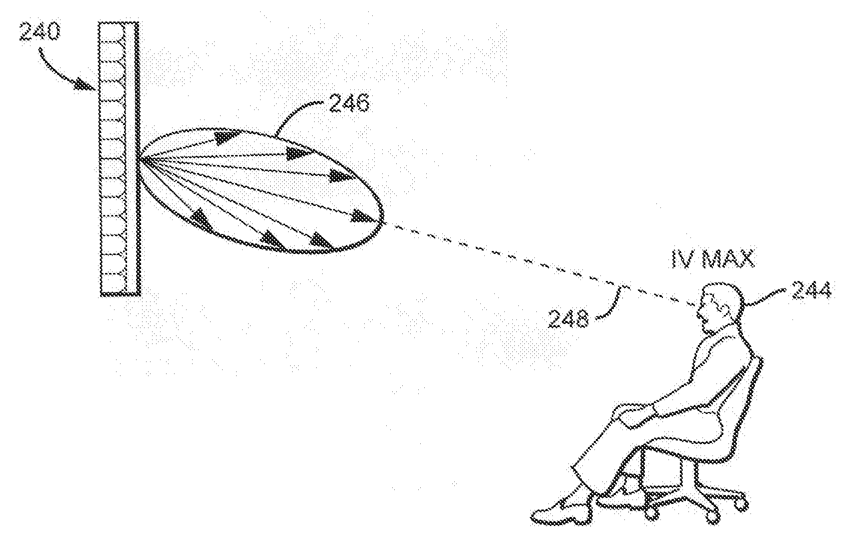
[0049]The present invention is directed to various embodiments of LEDs packages characterized by having the peak Iv and FFP emission characteristics shifted or tilted at an angle from the perpendicular centerline to the LED displays utilizing the LED packages. The LED displays according to the invention can use LED packages as their emitters, and by arranging the LED packages with a substantially similar shift or tilt in peak emission, the LED displays can provide peak emission having the same or similar shift or tilt.

[0050]In the some embodiments, the tilt in the emission shift of the LED displays is described in relation to the plane of the displays, and in particular in relation to a perpendicular to the plane of the displays. For flat displays, the plane of the display is the surface of the display and when the display is mounted to a flat surface this is typically parallel to the display's mounting surface. For curved displays, the plane is a tangent plane to the display surfac...


PUM


Abstract

LED packages and LED displays utilizing the LED packages are disclosed where the peak emission of the LED display can be tilted or shifted to customize its peak emission to the mounting height or location of the LED display. One embodiment of an LED display comprises a plurality of LED package where the peak emission from at least some of the LED packages is tilted off the package centerline. The LED packages are mounted within the display in such a way as to generate an image having a peak emission that is tilted off the perpendicular emission direction of the display.

Description

BACKGROUND OF THE INVENTION[0001]1. Field of the Invention[0002]This invention relates to light emitting diodes (LED or LEDs) and in particular displays utilizing LEDs.[0003]2. Description of the Related Art[0004]Light emitting diodes (LED or LEDs) are solid state devices that convert electric energy to light, and generally comprise one or more active layers of semiconductor material sandwiched between oppositely doped layers. When a bias is applied across the doped layers, holes and electrons are injected into the active layer where they recombine to generate light. Light is emitted from the active layer and from all surfaces of the LED.[0005]Technological advances over the last decade or more has resulted in LEDs having a smaller footprint, increased emitting efficiency, and reduced cost. LEDs also have an increased operation lifetime compared to other emitters. For example, the operational lifetime of an LED can be over 50,000 hours, while the operational lifetime of an incandesc...

Claims


Application Information

Patent Timeline
06 Jan 2011
Publication
US20110001149A1
IPC
H01L33/00
CPC
G09F9/33; H01L33/54; H01L33/60; G09F9/3026; H01L2924/0002; H01L33/48; H01L2924/00; Y10S362/80
Inventors
CHAN, CHI KEUNG; LAU, YUE KWONG