Phase modulation device for an ophthalmic instrument, ophthalmic instruments equipped with such device, and related calibration method

Active Publication Date: 2011-01-06
IMAGINE EYES
View PDF4 Cites 29 Cited by
  • Summary
  • Abstract
  • Description
  • Claims
  • Application Information

AI Technical Summary

Benefits of technology

[0038]It could have seemed obvious, in order to limit the visual discomfort of a patient while ensuring effective control of a phase modulation device, to improve the enslavement process described in the document FR2 866 551 by using for the measurement of eye aberrations, a source of illumination that is invisible to the eye, typically at an infrared wavelength greater than 900 nanometres. However, due to the eye's chromatism, enslavement of the modulation means carried out in the infrared would not necessarily have been valid for the main beam if the latter had a different wavelength, typically in the visible spectrum. Moreover, use of a secondary beam interacting with the eye necessarily limits the flux

Problems solved by technology

In all cases, aberrations of the different optical elements of the eye cause aberrations of the wave front of the main beam, which degrades the quality of the optical instrument.
Thus, in the case of retinal imaging, the image loses resolution and, in the case of the optical treatment of the eye, the quality of focusing the laser on the retina is degraded.
In the case of a visual simulation appliance operating in a closed loop, the problem generally faced is the need to direct light into the patient's eye, resulting in dazzling and thus disturbance to the simulation process, as well as creating a sensation of ocular discomfort.
In this case, no light is directed into the patient's eye but consequently, no wave front measurement is possible, as no light returns from the eye.
Such an approach has the draw

Method used


Image

  • Phase modulation device for an ophthalmic instrument, ophthalmic instruments equipped with such device, and related calibration method
  • Phase modulation device for an ophthalmic instrument, ophthalmic instruments equipped with such device, and related calibration method
  • Phase modulation device for an ophthalmic instrument, ophthalmic instruments equipped with such device, and related calibration method

Examples


Example

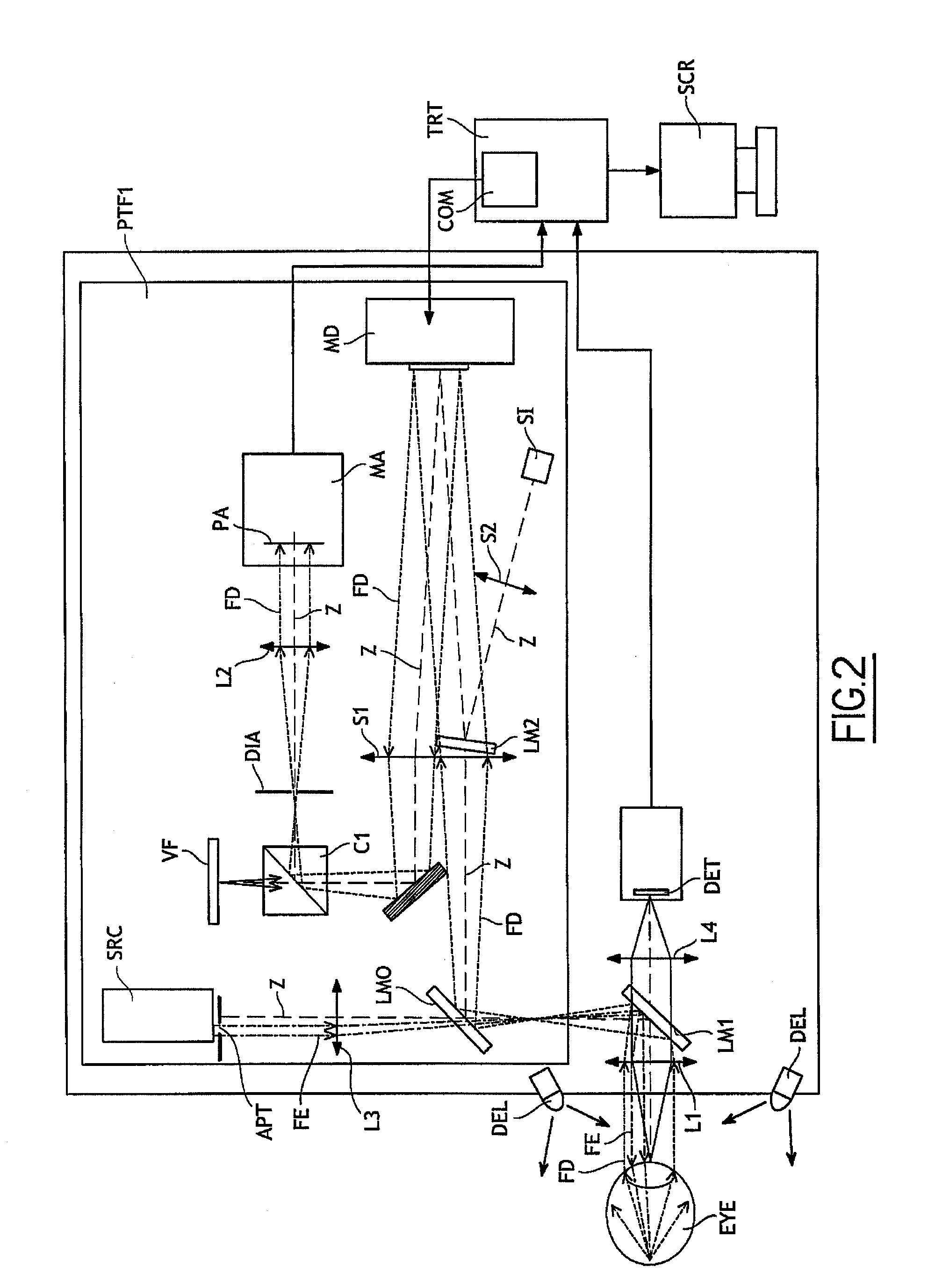
[0083]The first embodiment of the process according to the invention thus makes it possible to calibrate the device according to the invention, without using an artificial eye, and in the absence of the main beam FA.

Example

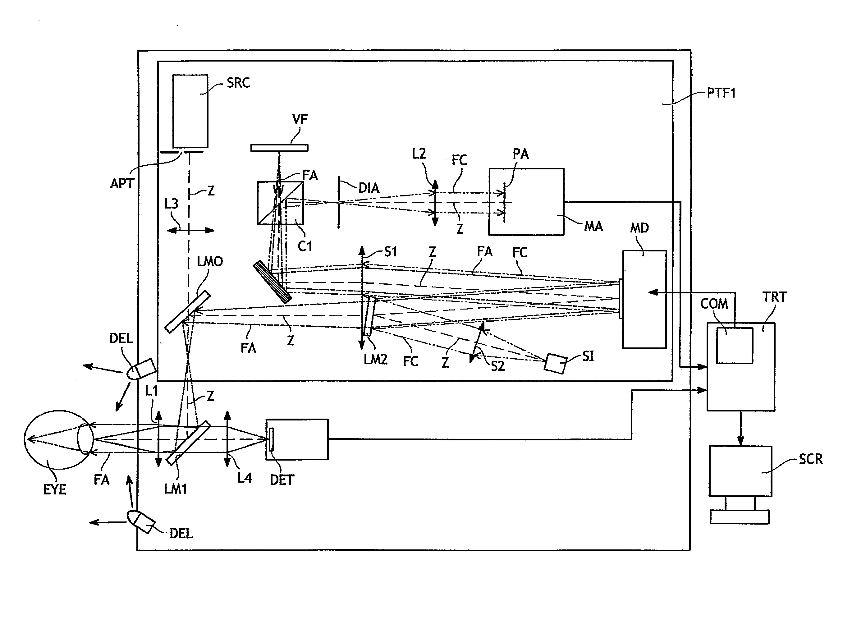
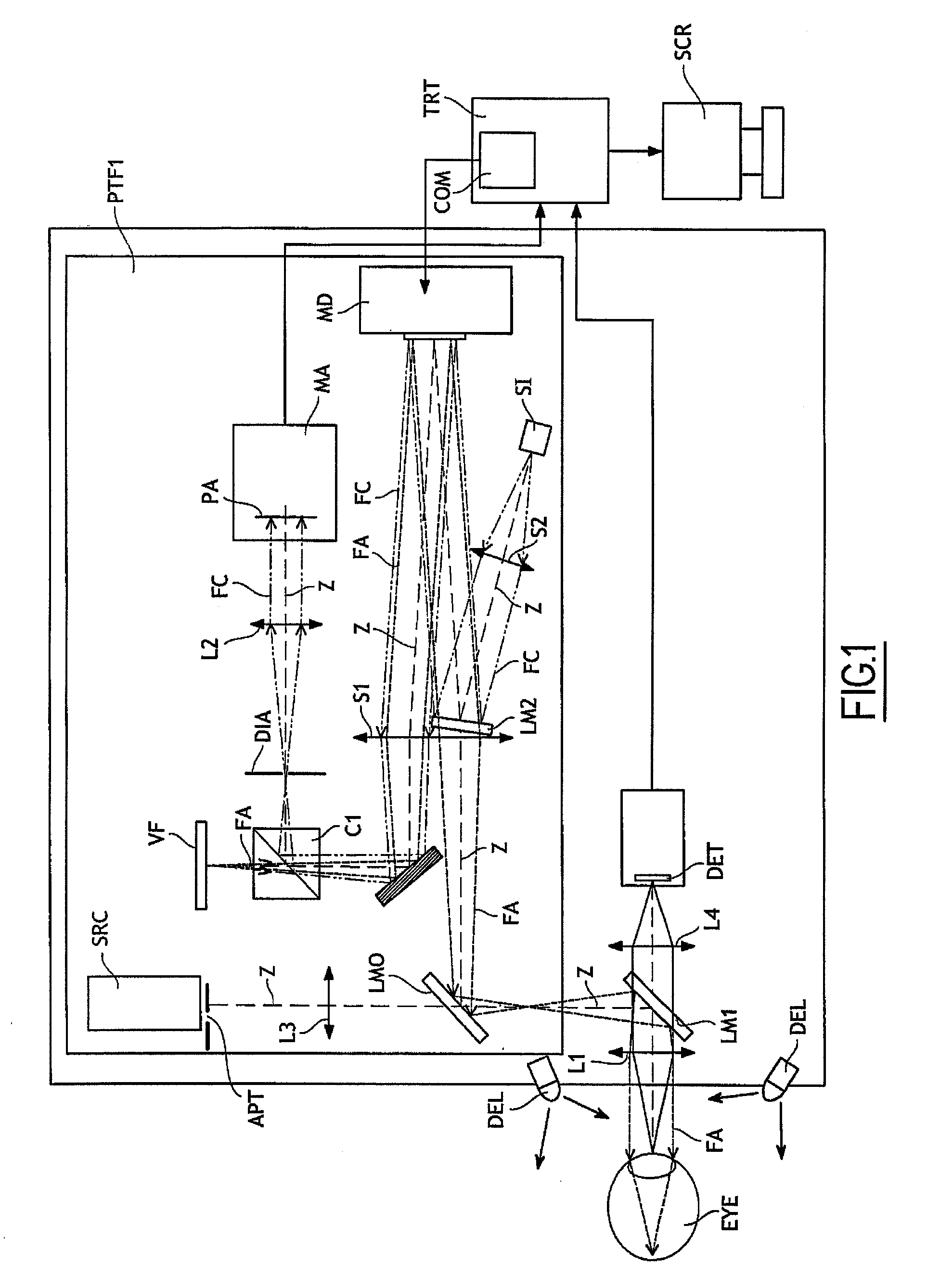
[0084]A second embodiment of the process according to the invention, implemented in the simulator according to the invention and shown in FIG. 1, comprises the following steps:[0085]controlling the modulation means according to the modulation instruction,[0086]positioning an eye to be examined at the output of the simulator according to the invention,[0087]emitting the measurement light beam FC,[0088]emitting the main light beam FA,[0089]modulating the phase of the wave front of the secondary beam, according to the modulation instruction, by the modulation means MD,[0090]modulating the phase of the wave front of the main light beam FA interacting with the eye EYE, according to a modulation instruction, the modulations of the main and measurement beams being simultaneous,[0091]measuring the phase modulation carried out by the modulation means on the secondary beam, and[0092]if the phase modulation carried out by the modulation means on the secondary beam is approximately equal to the...


PUM


Abstract

A phase modulation device implemented in an ophthalmic instrument using a main light beam interacting with an eye, the device including: an apparatus for modulating the phase of the wave front of the main light beam, a controller for controlling the phase modulation apparatus following a modulation instruction, and an analyzer for analyzing the thus-performed modulation of the phase of the wave front of the main light beam, further including emitting a secondary light beam, an apparatus for directing the secondary light beam along an optical path to the modulation apparatus, then to the analyzer, and in that the optical path does not pass through the eye, and in that the controller and the analyzer receiving the modulated secondary light beam cooperate, during a stage called a learning stage, to supply data regarding the response of the phase modulation apparatus to a set of predetermined modulation instructions.

Description

TECHNICAL FIELD [0001]The present invention relates to a phase modulation device for an ophthalmic instrument using a light beam interacting with an eye. It also relates to ophthalmic instruments implementing such a device, as well as to a calibration process for these ophthalmic instruments.[0002]The field of the invention is more particularly that of visual correction simulators and ophthalmic imaging devices, in particular for high-resolution retinal imaging.STATE OF THE PRIOR ART[0003]Ophthalmic instruments, such as for example instruments for retinal imaging or for optical laser treatment on the retina, operate with a main beam intended to pass through the various optical elements (cornea, crystalline lens, etc.) of a patient's eye, either by a beam incident on the eye (case of optical treatment of the retina), or as a beam emerging from the eye (case of retinal imaging).[0004]In all cases, aberrations of the different optical elements of the eye cause aberrations of the wave f...

Claims


Application Information

Patent Timeline
IPC IPC(8): A61B3/113A61B3/10A61F9/008
CPCA61B3/1015
Inventor LEVECQ, XAVIER
Owner IMAGINE EYES
Why Eureka
Try Eureka