Wide angle LED lamp structure

a led lamp and wide angle technology, applied in the direction of fixed installation, lighting and heating equipment, lighting support devices, etc., can solve the problems of uneven brightness, increased cost and waste of resources, and the majority of led lamps cannot adjust the brightness and illumination range, so as to achieve the effect of reducing the drooping of lamps

Inactive Publication Date: 2011-01-06
LI HONG TECHNOLOGICAL
View PDF2 Cites 73 Cited by
  • Summary
  • Abstract
  • Description
  • Claims
  • Application Information

AI Technical Summary

Benefits of technology

[0006]For achieving the object described above, the present invention utilizes an inclined angle of an LED holder to adjust the illumination range and reduce the dazzle through a reflection board and a lamp cover, and also controls the brightness of lamp by varying the number of LED bulbs on PCBs, so as to meet the requirements of energy saving and cost reduction.
[0007]The wide angle LED lamp structure of the present invention also can replace the LED holder for fixing PCBs by detachable holder pieces, so that the user can adjust the illumination range and brightness by replacing the holder so as to meet different demands, thereby reducing the cost.
[0010]2. The number of LED bulbs can be adjusted to achieve energy saving and cost reduction.
[0012]4. The dazzle of lamp can be effectively reduced by using the light reflection board and the lamp cover.

Problems solved by technology

In the market, most of LED lamps can not adjust the brightness and the illumination range due to the restriction of their fixed structure.
Conventionally, the number of LED bulbs in the lamp is constant which means it can not be reduced as demand changes and might increase cost and waste resource.
Besides, the conventional lamp always has fixed illumination angle and range, so that if the room for installing the lamp has insufficient height and wider space, the lamp might not illuminate the whole room, but if installing multiple lamps, the illumination ranges might be overlapped to cause uneven brightness and waste electricity.

Method used


Image

  • Wide angle LED lamp structure
  • Wide angle LED lamp structure
  • Wide angle LED lamp structure

Examples


Embodiment Construction

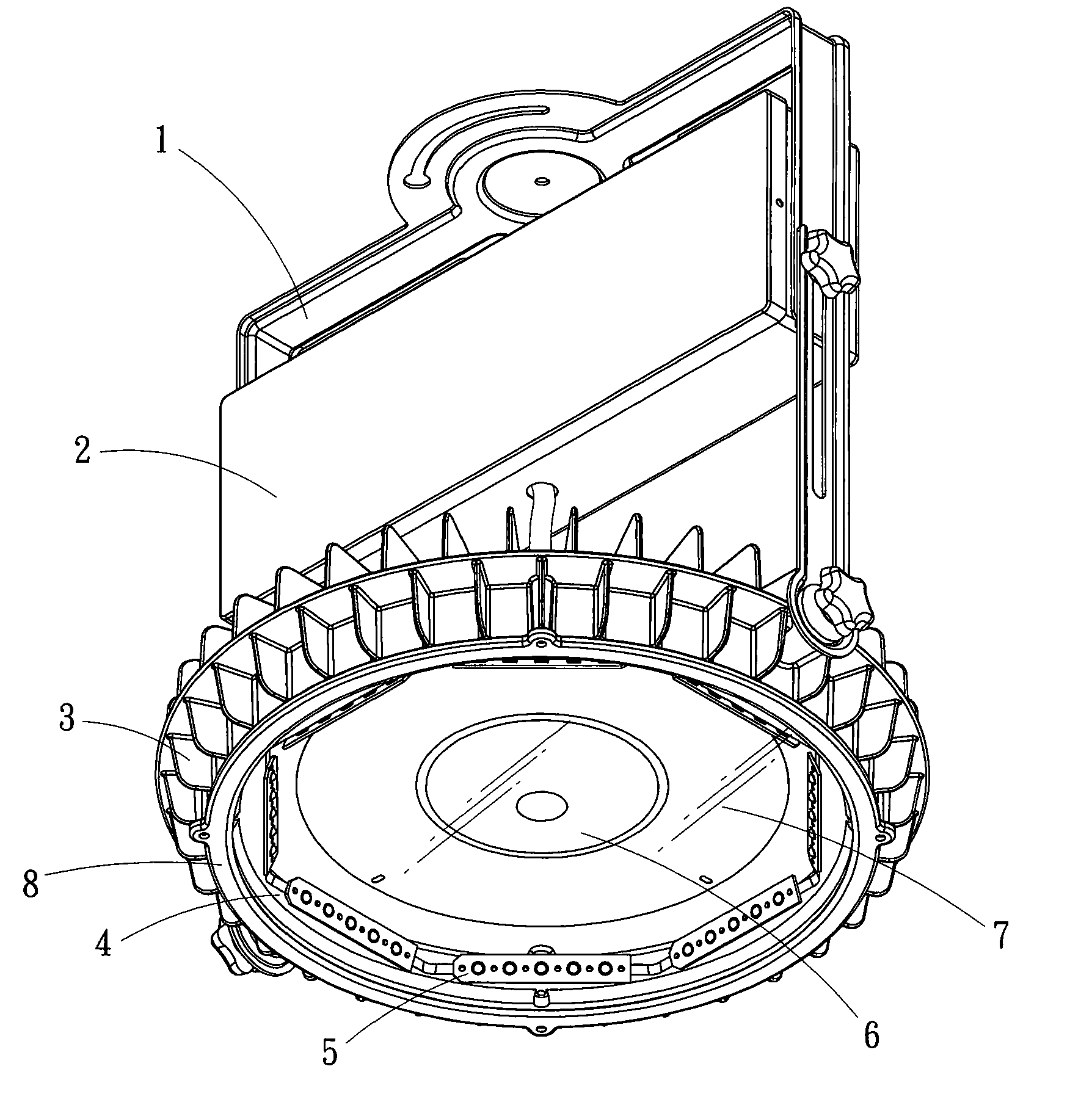
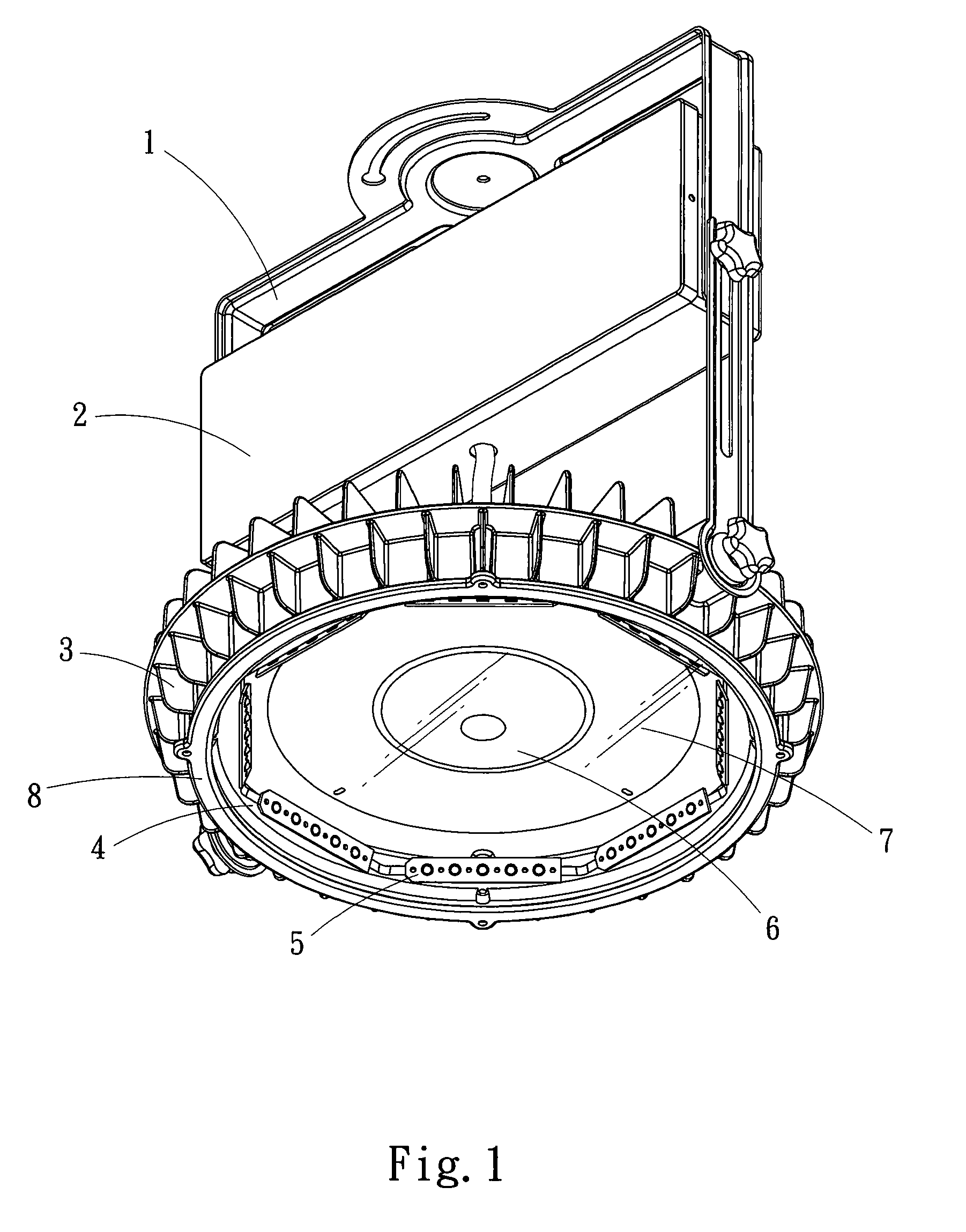
[0023]Please refer to FIG. 1. The wide angle LED lamp structure according to the present invention includes a fixture 1, a control box 2, a heat dissipation base 3, an LED holder 4, a plurality of PCBs 5, a light reflection board 6, a lamp cover 7, and a edge frame 8, wherein:

[0024]As shown in FIG. 2, FIG. 3 and FIG. 4, the fixture 1 includes a horizontal support 11 and two vertical supports 13 extended from two ends of the horizontal support 11, wherein a rotational disc 12 is mounted on the middle section of the horizontal support 11 for providing a turning function for the lamp as fixed on the wall. The control box 12 is mounted between the two vertical supports 13.

[0025]The heat dissipation base 3 is made of a metal having high heat dissipation efficiency, such as aluminum, copper and the likes. The heat dissipation base 3 is bolted between the two vertical supports 13 at the lower portion thereof, wherein the peripheral surface of the heat dissipation base 3 is surrounded by a ...


PUM


Abstract

A wide angle LED lamp structure provides a LED holder, which can be adjusted to have wide angle illumination range, embedded in a LED room of a heat dissipation base, cooperating with lamp cover and light reflection board, so that the illumination range becomes wider while maintaining the brightness even, and also the dazzle from LED lamp can be reduced. Besides, the LED holder can be replaced according to the different needs of illumination range, and the number of LED bulbs on the inclined plane of LED holder also can be varied in accordance with a user's demands, thereby enhancing the efficiency of each lamp.

Description

FIELD OF THE INVENTION[0001]The present invention is related to a wide angle LED lamp structure, and more particularly to a lamp structure which utilizes the LED holder to adjust the illumination angle and the brightness.BACKGROUND OF THE INVENTION[0002]In the market, most of LED lamps can not adjust the brightness and the illumination range due to the restriction of their fixed structure.[0003]Conventionally, the number of LED bulbs in the lamp is constant which means it can not be reduced as demand changes and might increase cost and waste resource. Therefore, when there is the need to vary the number of LED bulbs, the only way is to replace by another lamp with required number of LED bulbs.[0004]Besides, the conventional lamp always has fixed illumination angle and range, so that if the room for installing the lamp has insufficient height and wider space, the lamp might not illuminate the whole room, but if installing multiple lamps, the illumination ranges might be overlapped to...

Claims


Application Information

Patent Timeline
Patent Type & Authority Applications(United States)
IPC IPC(8): F21V29/00
CPCF21S8/036F21V19/001F21V19/02F21V19/045F21V29/77F21V23/008F21V29/004F21Y2101/02F21V21/14F21Y2115/10F21V19/0055F21V19/04F21V29/89
Inventor CHANG, KUN-JUNGJUAN, CHING-YUANLIN, KUO-CHUNJUAN, CHING-HUANG
Owner LI HONG TECHNOLOGICAL
Why Eureka
Try Eureka