Deblocking Apparatus and Associated Method

Active Publication Date: 2011-01-20
MEDIATEK INC
View PDF6 Cites 13 Cited by
  • Summary
  • Abstract
  • Description
  • Claims
  • Application Information

AI Technical Summary

Problems solved by technology

However, an annoying block artifact occurs after the decoder reconstructs the video signal such that one can observe obvious block boundaries since the source video signal is encoded on a block-by-block basis.
However,

Method used


Image

  • Deblocking Apparatus and Associated Method
  • Deblocking Apparatus and Associated Method
  • Deblocking Apparatus and Associated Method

Examples


Embodiment Construction

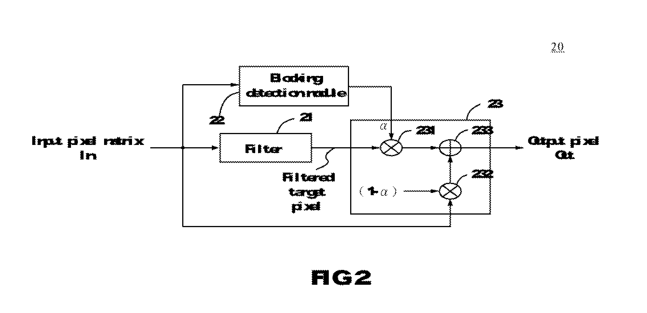
[0018]FIG. 2 is a circuit block diagram of a deblocking apparatus according to one embodiment of the present invention. The deblocking apparatus 20 comprises a filter 21, a blocking detection module 22 and a blending unit 23. The deblocking apparatus 20 receives an M×N pixel matrix In and outputs a deblocking pixel Out by deblocking a target pixel in the pixel matrix In. Each pixel has a pixel value P(i,j), where i=1 to M, and j=1 to N. Each pixel value represents R, G or B value in the R-G-B color space, where each of the R, G and B values is an integer, e.g., between 0 and 255. Alternatively, a pixel value P(i,j) represents Y, U and V value of a pixel in the Y-U-V color space, or a pixel value P(i,j) represents Y, Cb and Cr value of a pixel in the Y-Cb-Cr color space. Those skilled in the art shall conceive transformation among different color spaces, and herein no further details are given.

[0019]The target pixel is outputted to be a filtered target pixel through the filter 21. Th...


PUM


Abstract

A deblocking apparatus is provided. The deblocking apparatus includes a filter, a blocking detection module and a blending unit. The filter receives a target pixel of a pixel matrix to generate a filtered target pixel. The blocking detection module generates a deblocking intensity factor according to the pixel matrix. The blending unit receives the target pixel and the filtered target pixel, and dynamically blends the target pixel and the filtered target pixel to output an output pixel according to the deblocking intensity factor.

Description

CROSS REFERENCE TO RELATED PATENT APPLICATION[0001]This patent application is based on Taiwan, R.O.C. patent application No. 98124450 filed on Jul. 20, 2009.FIELD OF THE INVENTION[0002]The present invention relates to image processing, and more particularly to a deblocking apparatus and method.BACKGROUND OF THE INVENTION[0003]In the digital video signal processing, generally a digital video signal is encoded and compressed for the high-speed transmission in a bandwidth-limited channel. For example, Moving Picture Experts Group (MPEG) is a block-based video compression format.[0004]After being encoded and compressed, the video signal is transmitted through a transmission channel to a decoder, which then decodes and decompresses the video signal. However, an annoying block artifact occurs after the decoder reconstructs the video signal such that one can observe obvious block boundaries since the source video signal is encoded on a block-by-block basis.[0005]FIG. 1 is a block diagram o...

Claims


Application Information

Patent Timeline
IPC IPC(8): H04B1/66
CPCH04N19/117H04N19/86H04N19/80H04N19/14
Inventor HSU, HAN-JENLEE, WEI-KUO
Owner MEDIATEK INC
Why Eureka
Try Eureka