
Front foot air vent for automobile

a technology for automobiles and air vents, which is applied in vehicle components, vehicle heating/cooling devices, transportation and packaging, etc., can solve the problems of affecting the deteriorating the rigidity support force of the center support bracket 100, and affecting so as to improve the nvh characteristics of the steering device, improve the degree of freedom of design of the console, and reduce manufacturing costs

Inactive Publication Date: 2011-01-20
KIA MOTORS CORP
View PDF5 Cites 5 Cited by
  • Summary
  • Abstract
  • Description
  • Claims
  • Application Information

AI Technical Summary

Benefits of technology

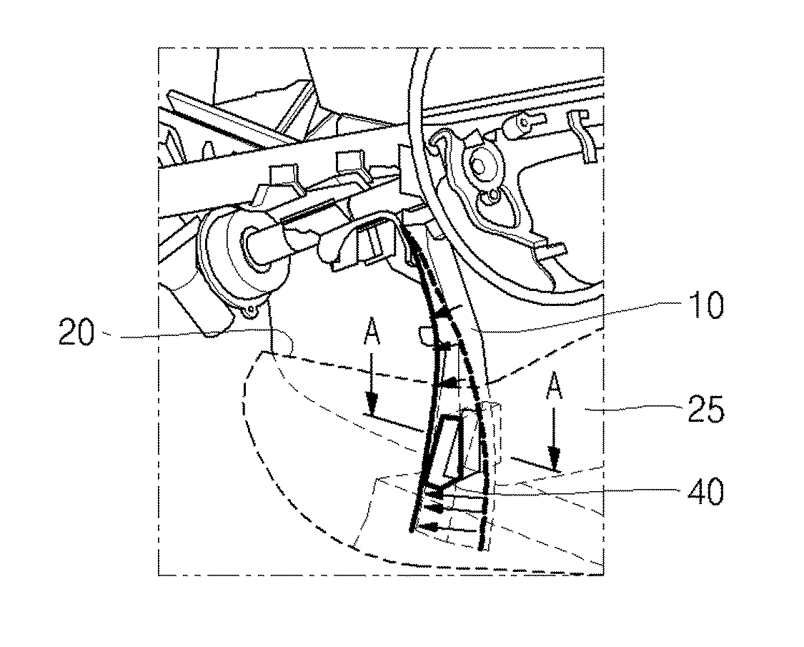
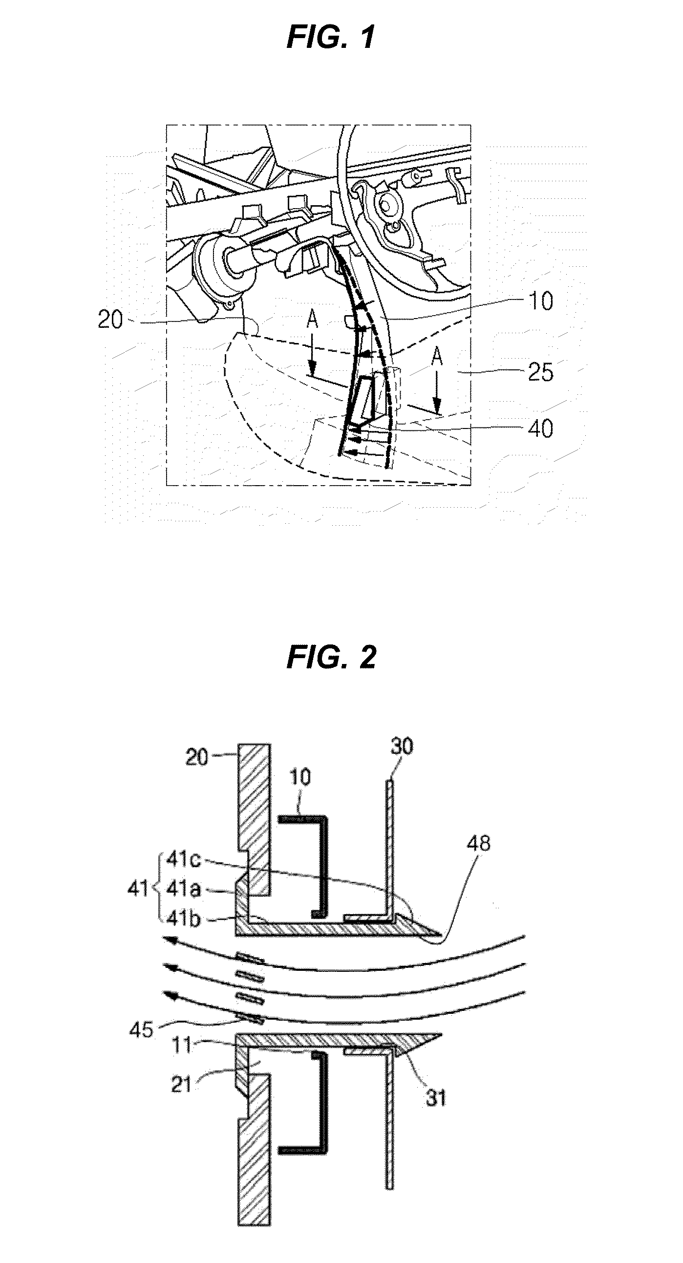
[0014]Various aspects of the present invention are directed to provide a front foot air vent for an automobile in which a center support bracket is provided at a passage of an air duct to be communicated with a foot air vent so that a front surface of a console can be closer to an instrument panel, thereby enhancing degree of freedom of design of the console and improving NVH characteristics of the steering device, and furthermore the console side cover and the console main cover are integrally formed and a grill member which is coupled to an air ventilation hole is separately formed so as to reduce manufacturing cost than a prior art in which a console cover is separately formed.

Problems solved by technology

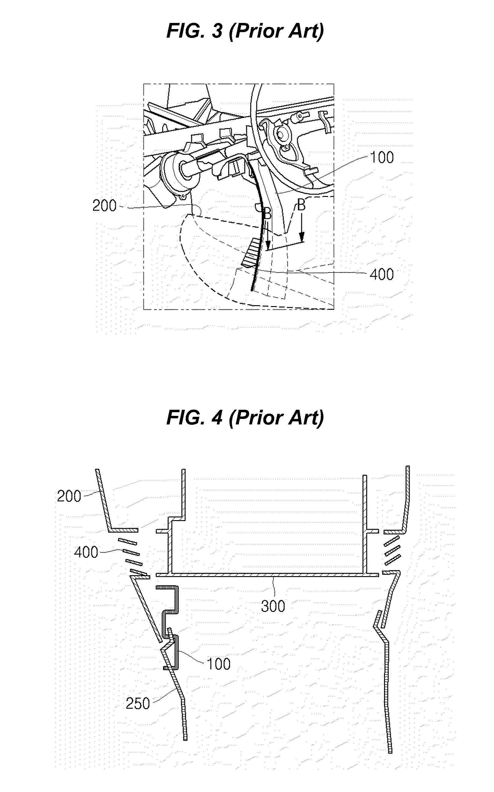
Thus, the rigidity support force of the center support bracket 100 is deteriorated, and NVH characteristic of steering is also deteriorated.
In addition, since the center support bracket 100 is designed to be bended toward the rearward of an automobile, there is a problem that the center support bracket 100 may interfere with a console main cover 250 which is positioned between a driver seat and a front passenger seat.
As such, the console side cover 200 and the console main cover 250 can not be integrally formed because of the discrepancy of the mold angle, and instead are separately formed and are then coupled to one another, so manufacturing cost is increased.

Method used


Image

  • Front foot air vent for automobile
  • Front foot air vent for automobile
  • Front foot air vent for automobile

Examples


Embodiment Construction

[0026]Reference will now be made in detail to various embodiments of the present invention(s), examples of which are illustrated in the accompanying drawings and described below. While the invention(s) will be described in conjunction with exemplary embodiments, it will be understood that present description is not intended to limit the invention(s) to those exemplary embodiments. On the contrary, the invention(s) is / are intended to cover not only the exemplary embodiments, but also various alternatives, modifications, equivalents and other embodiments, which may be included within the spirit and scope of the invention as defined by the appended claims.

[0027]Various exemplary embodiments of the present invention will hereinafter be described in detail with reference to the drawing.

[0028]FIG. 1 is a drawing showing a structure of a cabin around a front foot air vent for an automobile according to an exemplary embodiment of the present invention, and FIG. 2 is a sectional view along a...


PUM


Abstract

A front foot air vent for an automobile may include a center support bracket disposed between a console side cover and an air duct and provided with a through hole, wherein a discharge hole of the console side cover, a passage of the air duct and the through hole of the center support bracket are communicated with one another; and a grill member which is formed as a separate piece and includes an air passage therein, wherein the grill member is assembled to the discharge hole, the through hole and the passage so as to be communicated between the discharge hole of the console side cover and the passage of the air duct through the air passage of the grill member.

Description

CROSS-REFERENCE TO RELATED APPLICATION[0001]This application claims priority to Korean Patent Application No. 10-2009-0065071 filed in the Korean Intellectual Property Office on Jul. 16, 2009, the entire contents of which are incorporated herein for all purposes by this reference.BACKGROUND OF THE INVENTION[0002]1. Field of the Invention[0003]The present invention relates to a front foot air vent for an automobile, and more particularly to a front foot air vent for an automobile which is connected to an air conditioning device of an automobile and is positioned under a center support bracket in front of a driver seat and a front passenger seat.[0004]2. Description of Related Art[0005]Generally, an air conditioning device of an automobile is configured to introduce outside air into a cabin to cool or heat the cabin or to ventilate air inside the cabin to make the cabin comfortable.[0006]A foot air vent is integrally formed on a surface of a console side cover which is positioned at a...

Claims


Application Information

Patent Timeline
Patent Type & Authority Applications(United States)
IPC IPC(8): B60H1/24
CPCB60H1/3407B60H1/00564B60H1/242B60H1/00B60H1/34
Inventor KONG, BYUNG SEOK
Owner KIA MOTORS CORP
Learn More