Eureka AIR delivers breakthrough ideas for toughest innovation challenges, trusted by R&D personnel around the world.

Warming appratus for fuel gas cylinder

Inactive Publication Date: 2011-01-27
TSUNG KAO HSUNG
View PDF5 Cites 2 Cited by
  • Summary
  • Abstract
  • Description
  • Claims
  • Application Information

AI Technical Summary

Benefits of technology

[0012]It is an object of the present invention to provide a vaporization enhancer for fuel gas cylinder capable of automatically vaporizing liquid fuel gas that is difficult to be vaporized within the fuel gas cylinder for use in burners to achieve the purposes of energy saving and safety in use.

Problems solved by technology

However, in higher latitude areas or when the weather is cold, liquid fuel gas cannot be vaporized due to excessively low temperature thereby causing trouble in use.
Particularly after the liquid fuel gas has been used in a low-temperature environment for a period of time, the fuel gas cylinder exchanges heat with the external low temperature for a long time so that the liquid fuel gas within the fuel gas cylinder cannot absorb sufficient vaporization heat and the fuel gas supply is interrupted.
This causes much trouble for a user.
Furthermore, even if the external temperature is not lowered, when the fuel gas is used and reduced to a certain residual amount, the difference in pressure between the fuel gas cylinder and the external environment is decreased such that the residual fuel gas within the fuel gas cylinder is not easy to be released for use and still remains in the fuel gas cylinder, resulting in a waste of fuel gas.
Nevertheless, a fuel gas cylinder is often made of steel, which is very heavy and not easy to be moved.
Besides, not only is it difficult to roll such a heavy fuel gas cylinder from both sides or dip it into hot water, but also improper operation may wet the user's body or hurt the user's toes.
So, they are quite time-consuming and inconvenient.
Although the aforementioned prior art warmer can automatically warm a fuel gas cylinder when the environmental temperature is too low and provides a certain level of convenience in use, in fact, much potential risk exists.
If the aforementioned warmer is used to automatically warm the fuel gas cylinder filled with fuel gas, it is very easy to cause the danger of the fuel gas cylinder explosion due to the overpressure inside the cylinder.

Method used


Image

  • Warming appratus for fuel gas cylinder
  • Warming appratus for fuel gas cylinder
  • Warming appratus for fuel gas cylinder

Examples


Embodiment Construction

[0033]According to the technical means of the present invention, the implementation modes suitable for the present invention will be hereinafter described with reference to the drawings.

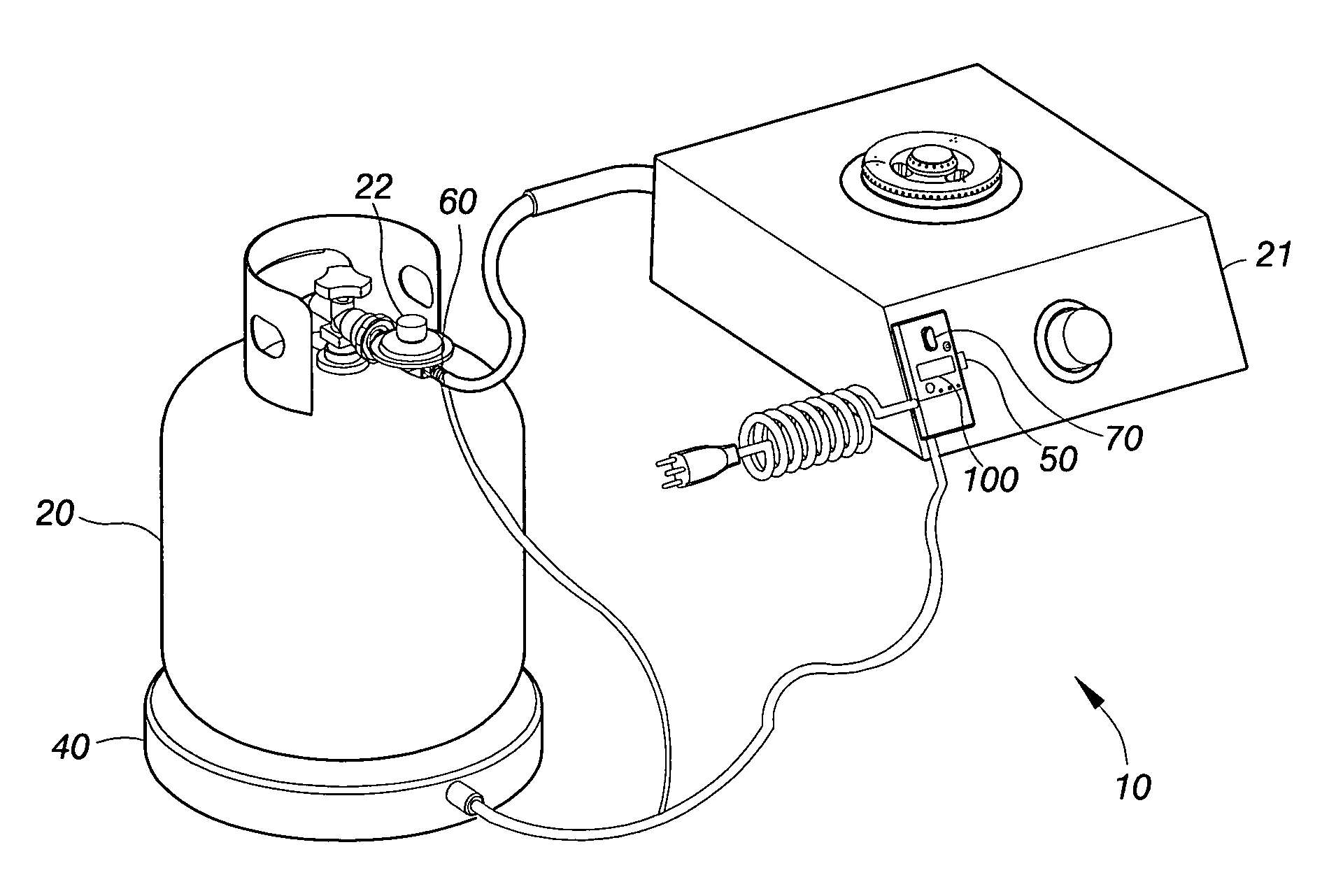
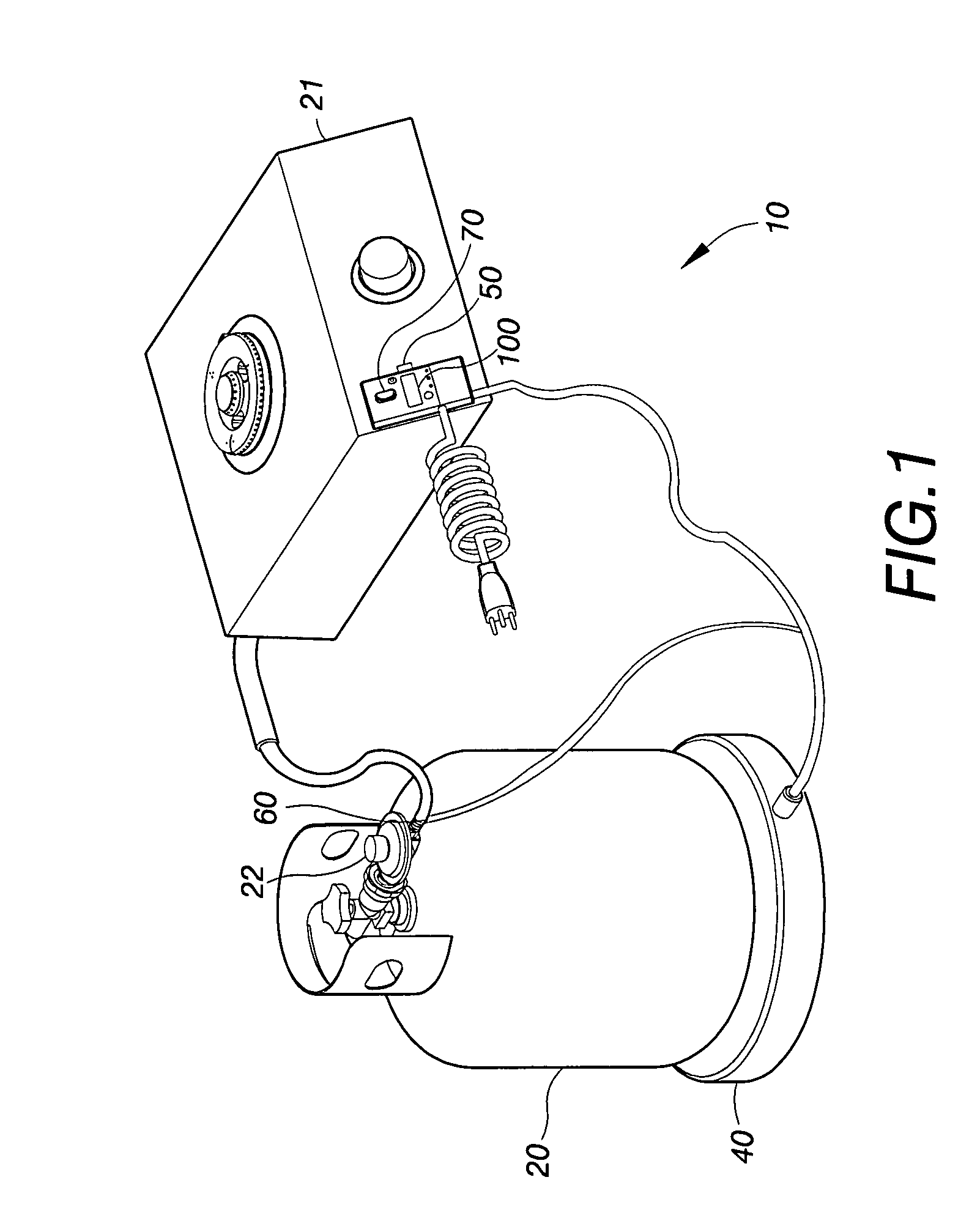
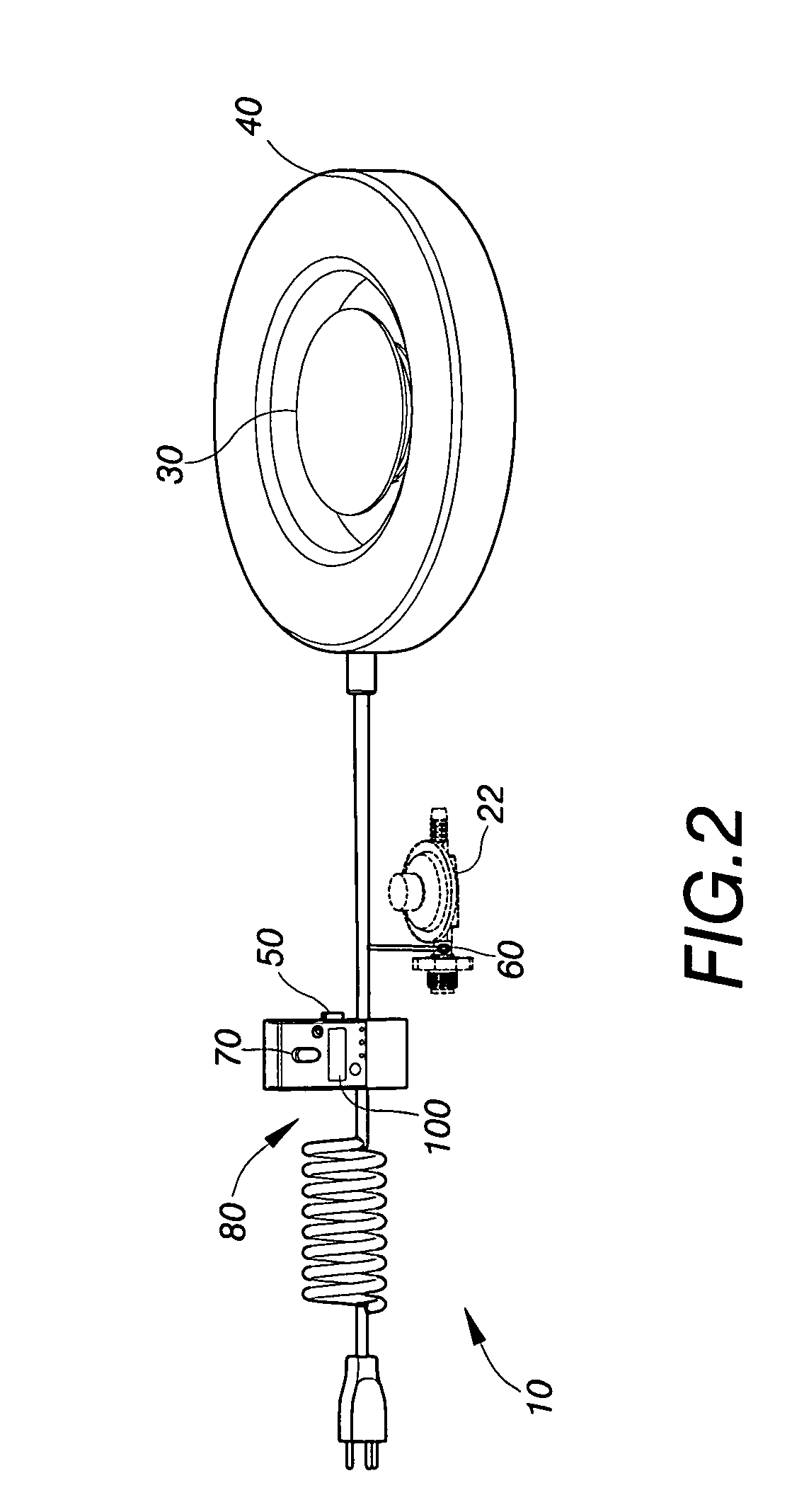
[0034]As illustrated in FIGS. 1 and 2, the vaporization enhancer 10 for fuel gas cylinder according to the present invention comprises a warmer 30 capable of warming the fuel gas cylinder 20, a fuel gas residual amount sensing unit 40 electrically connected to the warmer 30, a temperature control switch 50 and a flow-sensitive switch 60. Only when the fuel gas residual amount sensing unit 40, the temperature control switch 50, and the flow-sensitive switch 60 are simultaneously turned on, the warmer 30 warms the fuel gas cylinder 20 to vaporize the residual amount of liquid fuel gas within the fuel gas cylinder 20 for use in a burner 21.

[0035]The fuel gas residual amount sensing unit 40 used in the practice of the present invention may be a weight detector disposed at the bottom of the fuel gas cylin...


PUM


Abstract

Disclosed is a vaporization enhancer for fuel gas cylinder comprising a warmer capable of warming the fuel gas cylinder, a temperature control switch that is automatically turned on when the temperature is too low, a flow-sensitive switch that is turned on when the fuel gas flows out through the gas outlet pipe of the fuel gas cylinder, and a fuel gas residual amount sensing unit that is turned on when the amount of fuel gas stored in the fuel gas cylinder is too small. Only when the fuel gas residual amount sensing unit, the temperature control switch, and the flow-sensitive switch are simultaneously turned on, the warmer warms the fuel gas cylinder thereby enhancing the safety in use.

Description

BACKGROUND OF THE INVENTION[0001](a) Field of the Invention[0002]The present invention relates to equipment associated with a fuel gas cylinder, and more particularly to a vaporization enhancer for a fuel gas cylinder capable of warming a residual amount of liquid fuel gas within the fuel gas cylinder for use in burners.[0003](b) Description of the Prior Art[0004]Gas drums are common fuel facilities in modern homes. The drum gas is combustible fuel gas stored in a fuel gas cylinder. The fuel gas is often stored within the fuel gas cylinder in a liquid form at high pressure to increase the amount of fuel gas in the fuel gas cylinder. When it is desired to use the fuel gas, the pressure of liquid fuel gas within the fuel gas cylinder is reduced is and released through the gas outlet pipe of the fuel gas cylinder such that the liquid fuel gas is converted into a gaseous form for combustion use in burners.[0005]However, in higher latitude areas or when the weather is cold, liquid fuel g...

Claims


Application Information

Patent Timeline
IPC IPC(8): H05B3/02H05B1/02
CPCH05B1/0227
Inventor TSUNG, KAO HSUNG
Owner TSUNG KAO HSUNG
Why Eureka
Eureka Blog
Learn More