Tamper indicating optical security device

a technology of optical security and tampering, which is applied in the direction of identification means, instruments, non-fibrous pulp addition, etc., can solve the problems of not having a “peel to destroy” tamper indicating property, unauthorized interference with the device, and the device cannot be removed and re-adhered to another object,

Active Publication Date: 2011-01-27
VISUAL PHYSICS LLC (US)
View PDF99 Cites 91 Cited by
  • Summary
  • Abstract
  • Description
  • Claims
  • Application Information

AI Technical Summary

Benefits of technology

[0027](1) increasing or decreasing the stiffness (Young's modulus or tensile modulus), bond strength, or crosslink density of one or more target layers or interfaces relative to the remaining layers or interfaces of the security device;

Problems solved by technology

While such devices have been used in the past, they have not had, for example, a “peel to destroy” tamper indicating property.
By tampering is meant unauthorized interference with the device (i.e., attempts to remove the device from an object) whether for the purposes of counterfeiting, forgery or substitution.
The device, therefore, cannot be removed and re-adhered to another object, such as a counterfeit object, without the replacement being detected.
When the inventive device is adhered or bonded to a base material and an attempt is made to separate the device from the base material, the device is designed to fail, with failure generally occurring internally within and / or between the focusing element layer(s) and the image element layer(s).

Method used


Image

  • Tamper indicating optical security device
  • Tamper indicating optical security device
  • Tamper indicating optical security device

Examples


Embodiment Construction

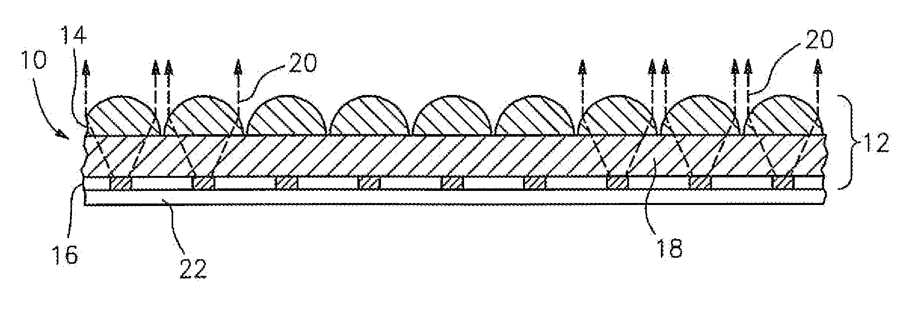
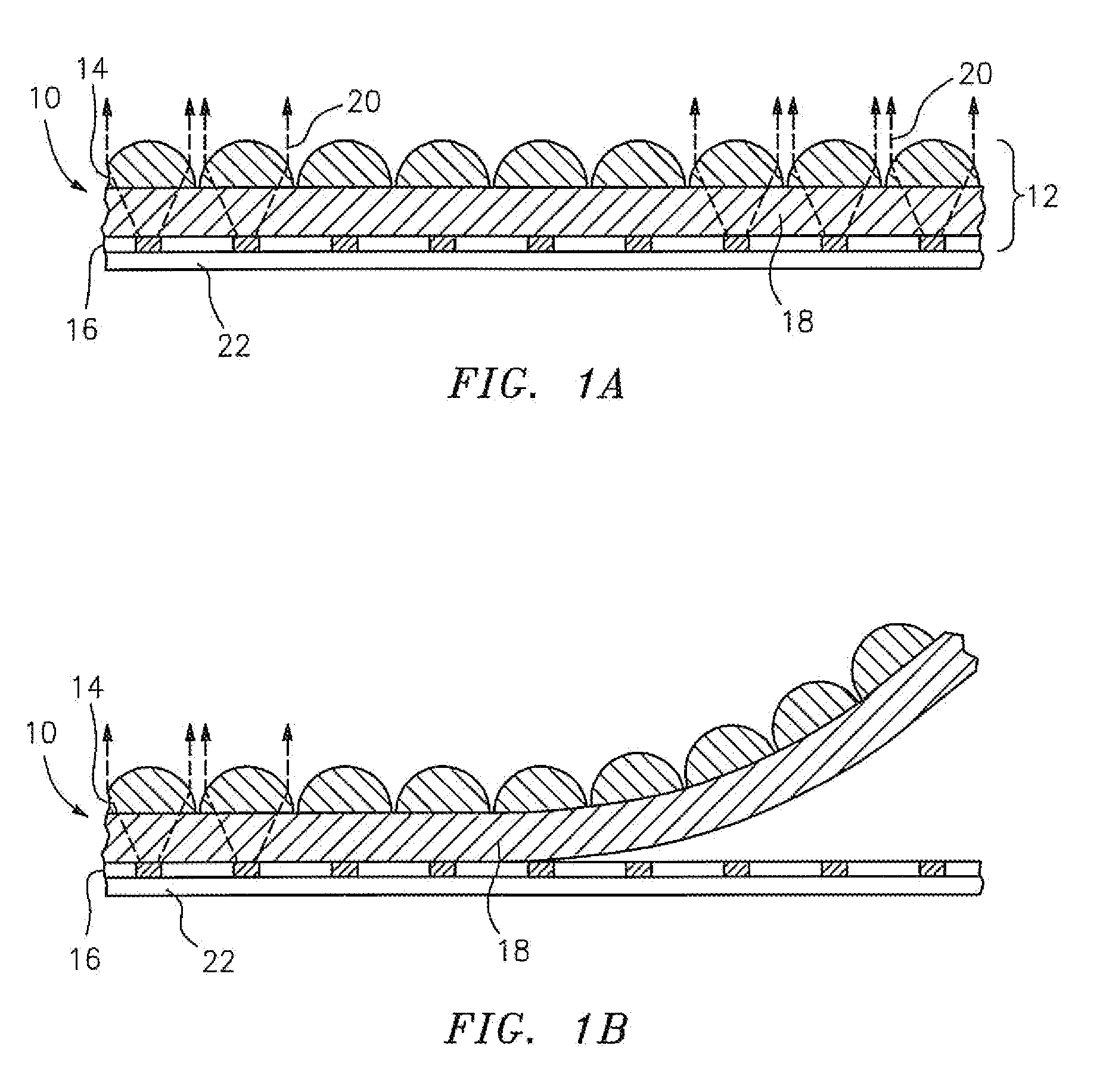
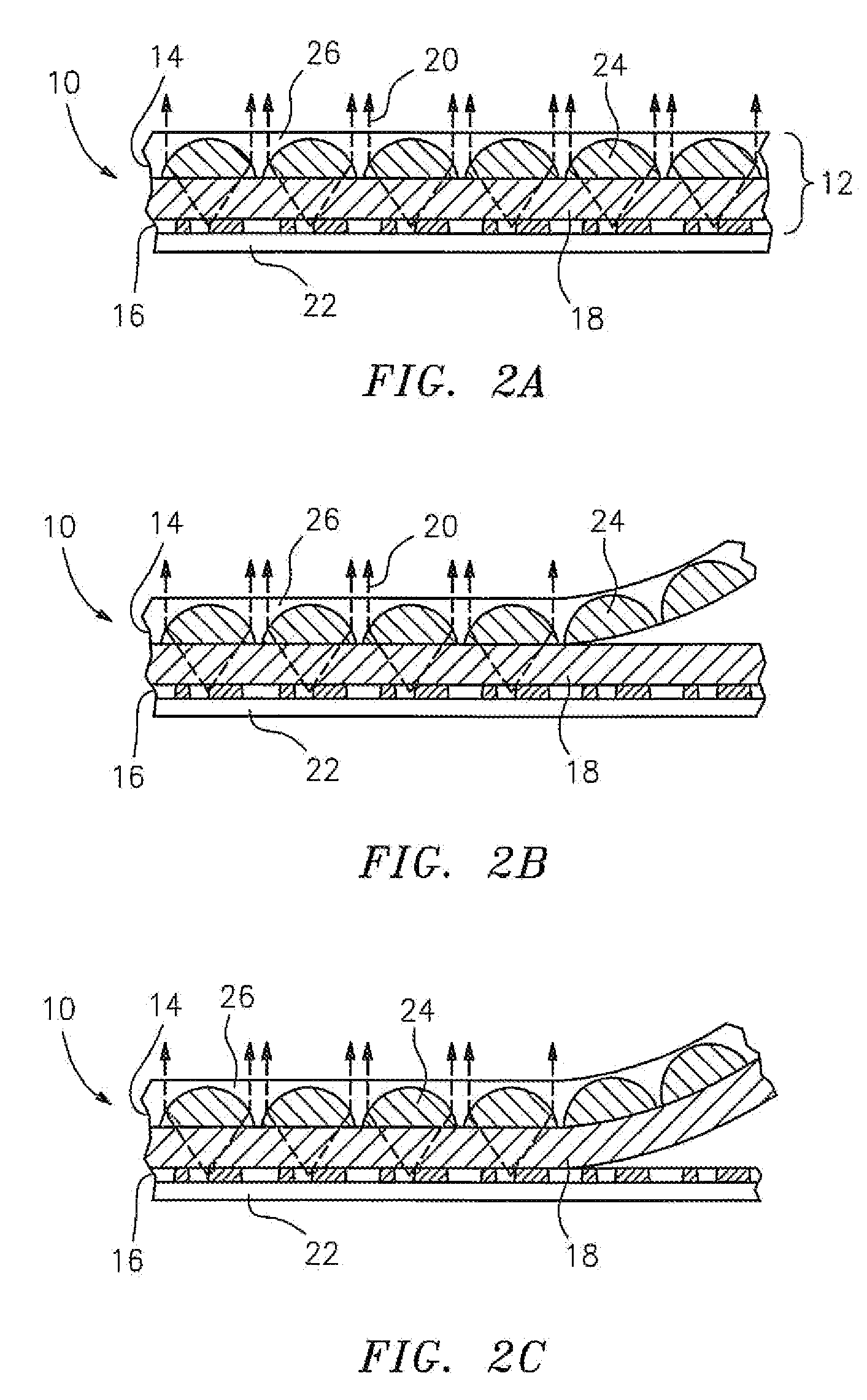
[0047]The present inventors, recognizing the usefulness of a “peel to destroy” feature, have developed a tamper indicating security device designed for intralayer and / or interlayer failure when an attempt is made to separate the device from an underlying base material.

[0048]The inventive device, which can take the form of, for example, a security strip, thread, patch, inlay, or overlay, is contemplated for use with, among other things, currency or banknotes, secure documents such as bonds, checks, travelers checks, identification cards, lottery tickets, passports, postage stamps, and stock certificates, as well as non-secure documents such as stationery items and labels. The inventive device is also contemplated for use with consumer goods as well as bags or packaging used with consumer goods.

[0049]Referring now to FIG. 1A of the drawings, an exemplary embodiment of the tamper indicating optical security device of the present invention is shown generally at 10. Device 10 basically c...


PUM

PropertyMeasurementUnit
focal lengthaaaaaaaaaa
tensile strengthaaaaaaaaaa

Abstract

A tamper indicating optical security device that operates to produce one or more synthetic images is provided. Any attempt to detach (e.g., forcibly remove) this device from an underlying base material will cause one or more layers of the security device to separate or delaminate, rending the device partially or totally inoperable. The inventive device is contemplated for use with, among other things, currency or banknotes, secure documents such as bonds, checks, travelers checks, identification cards, lottery tickets, passports, postage stamps, and stock certificates, as well as non-secure documents such as stationery items and labels. The inventive device is also contemplated for use with consumer goods as well as bags or packaging used with consumer goods.

Description

RELATED APPLICATIONS[0001]This application is a continuation-in-part of U.S. patent application Ser. No. 11 / 771,623, filed Jun. 29, 2007, and of U.S. patent application Ser. No. 11 / 932,468, filed Oct. 31, 2007, both of which claim priority to U.S. patent application Ser. No. 10 / 995,859, filed Nov. 22, 2004 (now U.S. Pat. No. 7,333,268), which claims priority to U.S. Provisional Patent Application Ser. No. 60 / 524,281, filed Nov. 21, 2003, U.S. Provisional Patent Application Ser. No. 60 / 538,392, filed Jan. 22, 2004, and U.S. Provisional Patent Application Ser. No. 60 / 627,234, filed Nov. 12, 2004, all of which are hereby incorporated herein by reference in their entirety, and this application claims benefit of and priority to U.S. Provisional Patent Application Ser. No. 61 / 233,264, filed Aug. 12, 2009, which is incorporated herein by reference in its entirety.TECHNICAL FIELD[0002]The present invention generally relates to a tamper indicating optical security device that operates to pro...

Claims


Application Information

Patent Timeline
Patent Type & Authority Applications(United States)
IPC IPC(8): G02B27/10G02B27/12G02B27/14B42D15/00B32B7/06
CPCB42D2035/44G02B3/0075B42D2035/20Y10T156/1153D21H21/44G03H2223/19G02B27/2214Y10T156/1158G03H1/0256D21H21/40G09F3/0376B42D25/29G02B3/0056G02B3/0031B29D11/00278B29D11/0073G02B30/27B42D25/351B42D25/373B42D25/47B42D25/21
Inventor STEENBLIK, RICHARD A.HURT, MARK J.JORDAN, GREGORY R.CAPE, SAMUEL M.
Owner VISUAL PHYSICS LLC (US)
Why Eureka
Try Eureka