Electric and Ballistic Connection Through A Field Joint

a field joint and electric and ballistic connection technology, applied in the direction of coupling device connection, engagement/disengagement of coupling parts, and borehole/well accessories, etc., can solve the problems of twisted wires of the circuit b>14/b> that pass between adjacent connector subs b>13/b> and guns b>6/b> during assembly

Active Publication Date: 2011-02-03
BAKER HUGHES INC
View PDF14 Cites 88 Cited by
  • Summary
  • Abstract
  • Description
  • Claims
  • Application Information

AI Technical Summary

Benefits of technology

[0009]Disclosed herein is a tool string of connected bodies with connections that can transmit signals and also transfer ballistic charges between the bodies. The signals can be electrical, electromagnetic, full spectrum light waves, radio waves, or combinations thereof. Also disclosed herein is a perforating system having annular connectors for attachment between adjacent perforating guns and connectors. The connectors include male and female connectors with respective outer and inner contact surfaces. In an embodiment, the connectors include attachment for detonator and/or booster charges for transferring ballistic detonations between the perforating gun and connector sub. In an example, disclosed is a perforating system that includes a first perforating string member having a first annular electrical contact, a first signal member in communication with the first annular electrical contact, and an end having a first connection fitting, a second perforating string member having a second annular element contact, a second signal member in communication with the second annular electrical contact, and an end having a second connection fitting selectively in a configuration attached with the end having a first connection fitting, so that when the end having a second connection fitting is attached to the end having the first connection fitting, the first and second annular electrical contacts are, in an embodiment, coaxially contacting, and the first and second signal members are in electrical communication. The perforating string members can be a perforating gun, a connecting sub, a booster sub, or a control sub. The first annular electrical contact may be a sleeve and the second annular electrical contact can be a split ring coaxially insertable within the sleeve to foam an interference fit. The perforating system may further include an annular contact body threadingly attached to threads formed on an inner surface of the firs

Problems solved by technology

Moreover, wires of the circuit 14 that pass between adjacent connector su

Method used


Image

  • Electric and Ballistic Connection Through A Field Joint
  • Electric and Ballistic Connection Through A Field Joint
  • Electric and Ballistic Connection Through A Field Joint

Examples


example signal

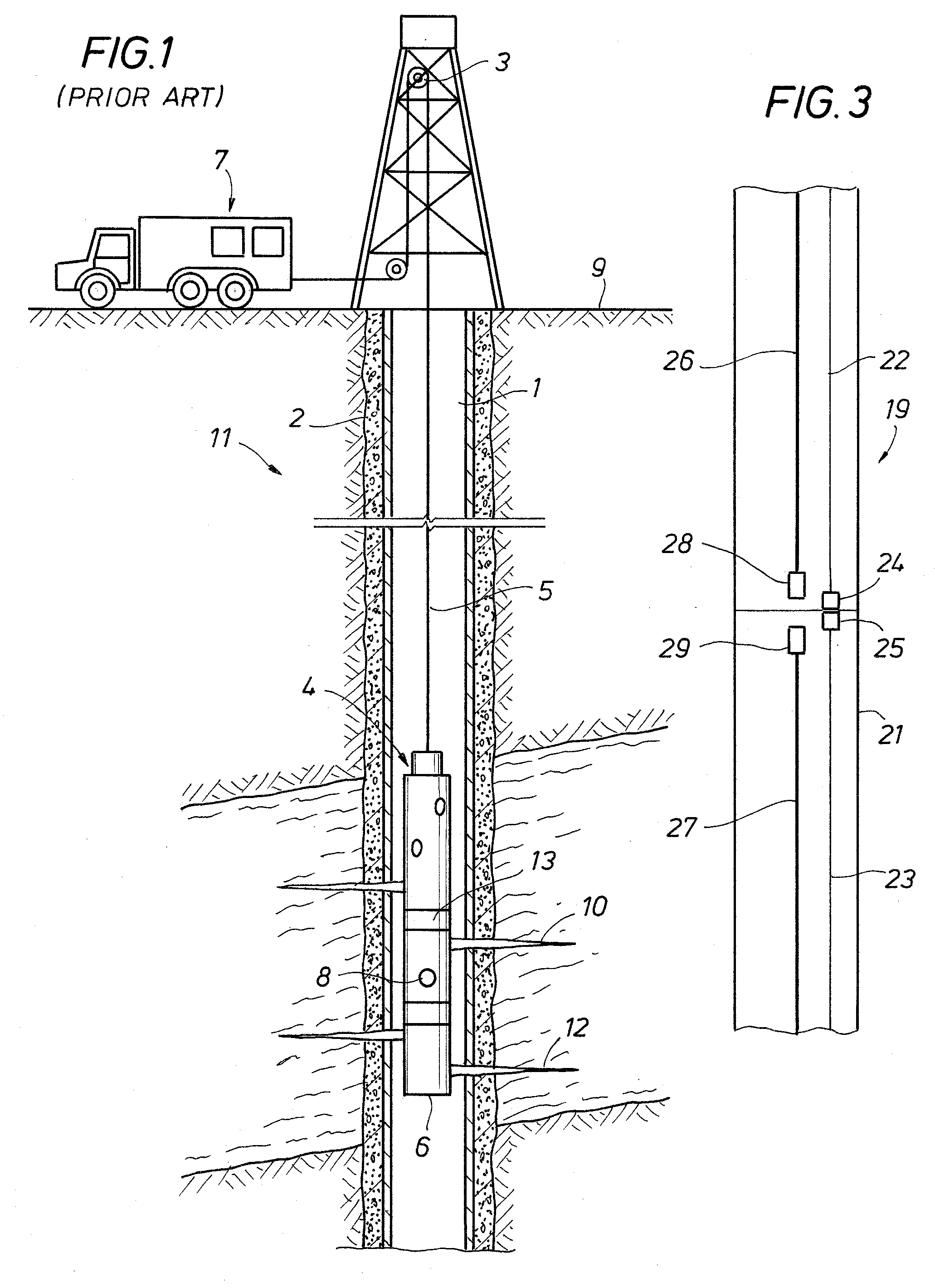
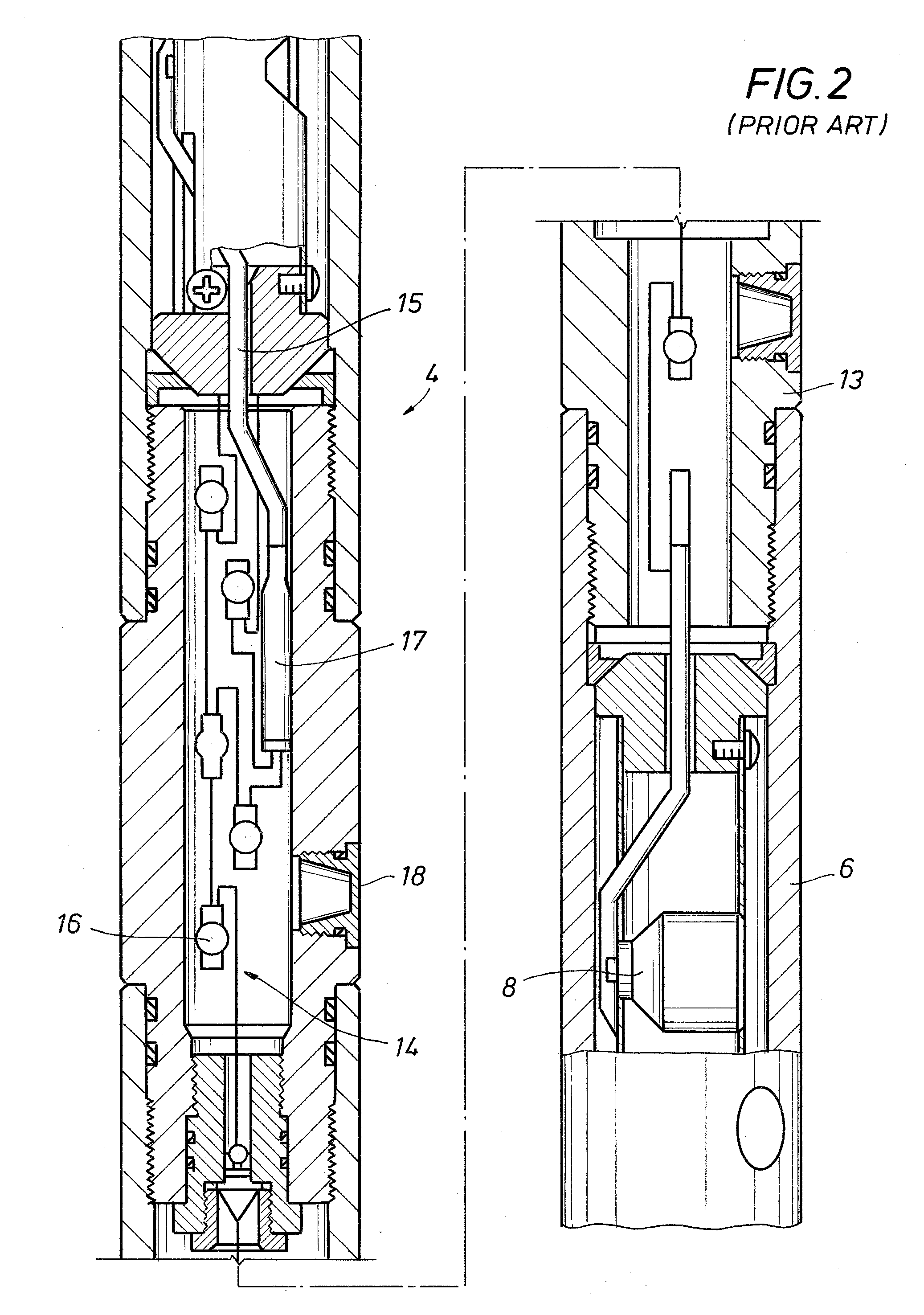
[0026 connectors 24, 25 include electrically conducting members that register with one another and are brought into electrical contact / communication when the bodies 20, 21 are attached. Optionally, the connectors 24, 25 may be annular rings (not shown) that connect with attachment of the bodies 20, 21, fiber optic couplers, and / or receiver transmitters. Yet further optionally, the bodies 20, 21 may include additional signal lines and connectors.

[0027]Further illustrated in the bodies 20, 23 are detonation cords 26, 27 through which a detonation signal may be transmitted. A first booster 28 is shown on the end of the detonation cord 26 adjacent the connection between the bodies 20, 21. In the embodiment of FIG. 3, a detonation signal may travel on the end of the detonation cord 26 opposite the detonator 28. On reaching the first booster 28, the detonation signal initiates the first booster 28 that in turn forms a ballistic detonation that transmits through the connection between the ...


PUM


Abstract

A perforating system having annular connectors for attachment between adjacent perforating guns and connectors. The connectors include male and female connectors with respective outer and inner contact surfaces. The connectors also include attachment for electrical detonators and/or booster charges for transferring ballistic detonations between the perforating gun and connector sub.

Description

BACKGROUND[0001]1. Field of Invention[0002]The invention relates generally to the field of oil and gas production. More specifically, the present invention relates to a perforating system having signal circuit connectors on adjacent members of a perforating string that can be put into direct contact.[0003]2. Description of Prior Art[0004]Perforating systems are used for the purpose, among others, of making hydraulic communication passages, called perforations, in wellbores drilled through earth formations so that predetermined zones of the earth formations can be hydraulically connected to the wellbore. Perforations are needed because wellbores are typically completed by coaxially inserting a pipe or casing into the wellbore. The casing is retained in the wellbore by pumping cement into the annular space between the wellbore and the casing. The cemented casing is provided in the wellbore for the specific purpose of hydraulically isolating from each other the various earth formations...

Claims


Application Information

Patent Timeline
IPC IPC(8): E21B43/11H01R13/62
CPCE21B43/1185H01R2103/00H01R24/38
Inventor MCCANN, JASONSLOAN, MARKWEEKLEY, JAMES A.
Owner BAKER HUGHES INC
Why Eureka
Try Eureka