

Downhole debris removal tool
a technology for debris removal and downholes, applied in fluid removal, borehole/well accessories, sealing/packing, etc., can solve the problems of corroding the casing, preventing the free movement of tools, and affecting the production of hydrocarbons or tools
Inactive Publication Date: 2011-02-03
MI +1
View PDF28 Cites 49 Cited by
- Summary
- Abstract
- Description
- Claims
- Application Information
AI Technical Summary
Benefits of technology
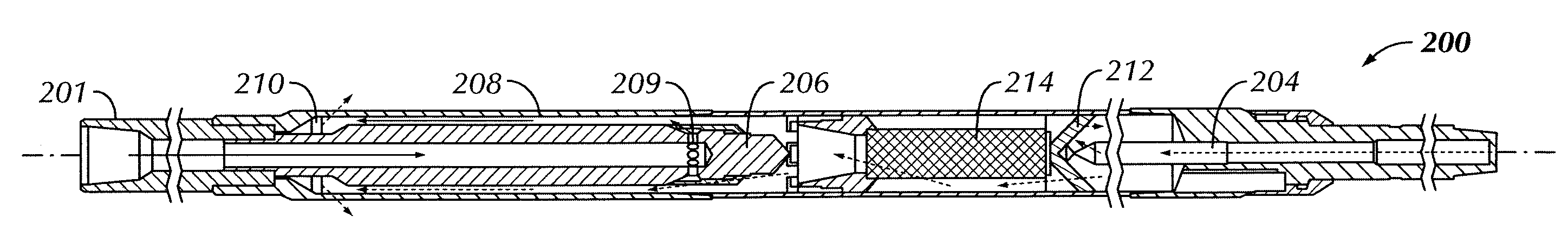
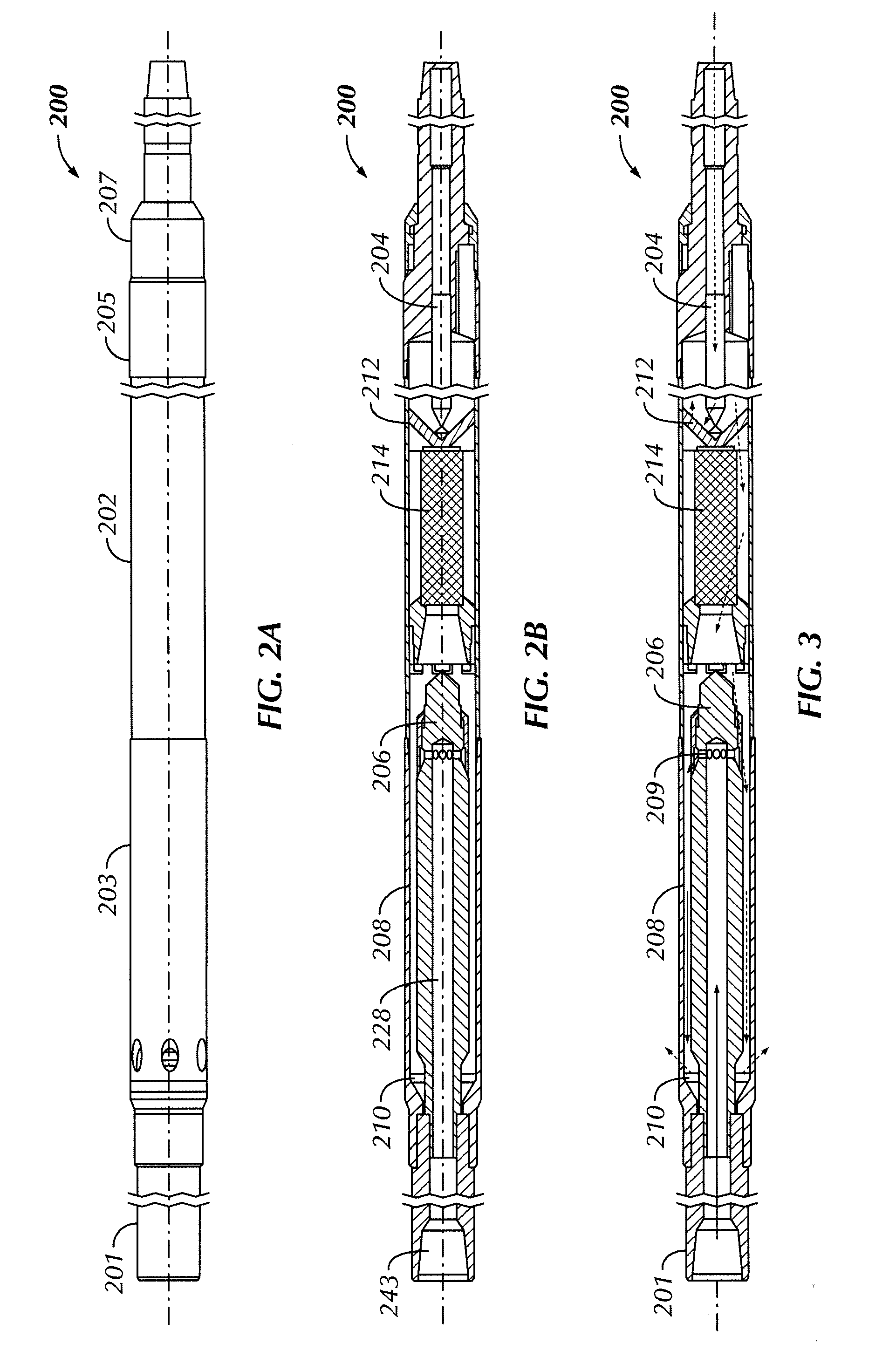
[0010]In another aspect, embodiments disclosed herein relate to a method of removing debris from a wellbore including the steps of lowering a downhole debris removal tool into the wellbore, the downhole debris removal tool having an annular jet pump sub, a mixing tube, a diffuser, and a suction tube, flowing a fluid through a bore of the annular jet pump sub, jettin
Problems solved by technology
For example, accumulation of debris can prevent free movement of tools through the wellbore during operations, as well as possibly interfere with production of hydrocarbons or damage tools.
Potential debris includes cuttings produced from the drilling of the wellbore, metallic debris from the various tools and components used in operations, and corrosion of the casing.
Smaller debris may be circulated out of the well bore
Method used
View moreImage
Smart ImageViewing Examples

Examples
 PUM
 Abstract
A downhole debris recovery tool including a ported sub coupled to a debris sub, a suction tube disposed in the debris sub, and an annular jet pump sub disposed in the ported sub and fluidly connected to the suction tube is disclosed. A method of removing debris from a wellbore including the steps of lowering a downhole debris removal tool into the wellbore, the downhole debris removal tool having an annular jet pump sub, a mixing tube, a diffuser, and a suction tube, flowing a fluid through a bore of the annular jet pump sub, jetting the fluid from the annular jet pump sub into the mixing tube, displacing an initially static fluid in the mixing tube through the diffuser, thereby creating a vacuum effect in the suction tube to draw a debris-laden fluid into the downhole debris removal tool, and removing the tool downhole debris removal tool from the wellbore after a predetermined time interval is also disclosed. Further, an isolation valve including a housing, an inner tube disposed coaxially with the housing, and a gate, wherein the gate is configured to selectively close an annular space between the housing and the inner tube is disclosed.
Description
BACKGROUND OF INVENTION[0001]1. Field of the Invention[0002]Embodiments disclosed herein generally relate to a downhole debris retrieval tool for removing debris from a wellbore. Further, embodiments disclosed herein relate to a downhole tool for debris removal with maximum efficiency at a low pump rates.[0003]2. Background Art[0004]A wellbore may be drilled in the earth for various purposes, such as hydrocarbon extraction, geothermal energy, or water. After a wellbore is drilled, the well bore is typically lined with casing. The casing preserves the shape of the well bore as well as provides a sealed conduit for fluid to be transported to the surface.[0005]In general, it is desirable to maintain a clean wellbore to prevent possible complications that may occur from debris in the well bore. For example, accumulation of debris can prevent free movement of tools through the wellbore during operations, as well as possibly interfere with production of hydrocarbons or damage tools. Poten...
Claims
Login to View More Application Information
Patent Timeline
 IPC IPC(8): E21B31/00E21B34/00
CPCE21B37/00E21B34/06
InventorWOLF, JOHN C.TELFER, GEORGEATKINS, JAMES
OwnerMI