Emergency isolation valve controller with integral fault indicator

a fault indicator and valve controller technology, applied in the field of valve controllers, can solve the problems of device being monitored out of service or burned out, and achieve the effect of improving monitoring performan

Active Publication Date: 2006-10-05
SAUDI ARABIAN OIL CO
View PDF27 Cites 44 Cited by
  • Summary
  • Abstract
  • Description
  • Claims
  • Application Information

AI Technical Summary

Benefits of technology

[0028] The present invention comprehends an emergency isolation valve controller with an integral function indicator which is locally positioned substantially adjacent to the safety devices, such as an EIV, to provide on-board diagnostics and local indications of detected faults, and to provide improved performance in monitoring and detecting faults in a chemical processing or other facility.
[0029] The present invention extends the capabilities of smart valve controllers to incorporate logic and local interface capabilities required to perform a safety instrumented function associated with an emergency isolation valve within the smart valve controller. The use of the present invention reduces the complexity of the plant-wide emergency shutdown system I / O connections required for each smart valve.
[0030] The present invention includes a local logic solver operating with a local smart valve controller to control and test a local field-mounted emergency isolation (or interrupt) valve (EIV) device that provides a local indication of trouble on the device, in the field. Accordingly, the operation of the overall system is simpler, in that there is no longer a need to use an external computer to diagnose the problem. In addition, technicians and operators in the field are alerted to a serious problem locally so that they can promptly take any necessary safety precautions, and / or undertake other appropriate action, including notifying a specialist to further diagnose the problem.
[0032] By providing steady ON, flashing, or steady OFF states in close proximity, e.g., substantially adjacent to the device being monitored, the condition of the device can easily be determined when operators or maintenance personnel are performing routine visual checks. Accordingly, the operating state of the indicator light of the present invention alerts the responsible operators, safety inspectors and other personnel when a particular device is operating in a seriously degraded state.
[0036] In addition, the present invention is useful for tracking faults and for verifying safety system performance. Since a plant process or other production system must have its safety systems checked and maintained routinely to ensure their proper functioning at the required level of performance, for example, in accordance with the original plant safety guidelines, the present invention serves to provide the required documentation of system performance. When a dangerous fault in a safety device is detected, an internal systems clock registers or records data corresponding to the time that the fault is detected, and this so-called time stamping will continue until the fault is corrected. In this way, the time that the safety device was operating in a disabled state can be tracked and documented so that the impact on the overall safety instrumentation system performance can be more accurately evaluated. Furthermore, the running clock and time-stamping feature of the present invention is performed locally at the device being monitored.

Problems solved by technology

In addition, when the normally steady ON indicator light is in a steady OFF state, the illumination device, such as a lamp of the indicator light, has either burned out or the device being monitored is out of service.

Method used


Image

  • Emergency isolation valve controller with integral fault indicator
  • Emergency isolation valve controller with integral fault indicator
  • Emergency isolation valve controller with integral fault indicator

Examples


Embodiment Construction

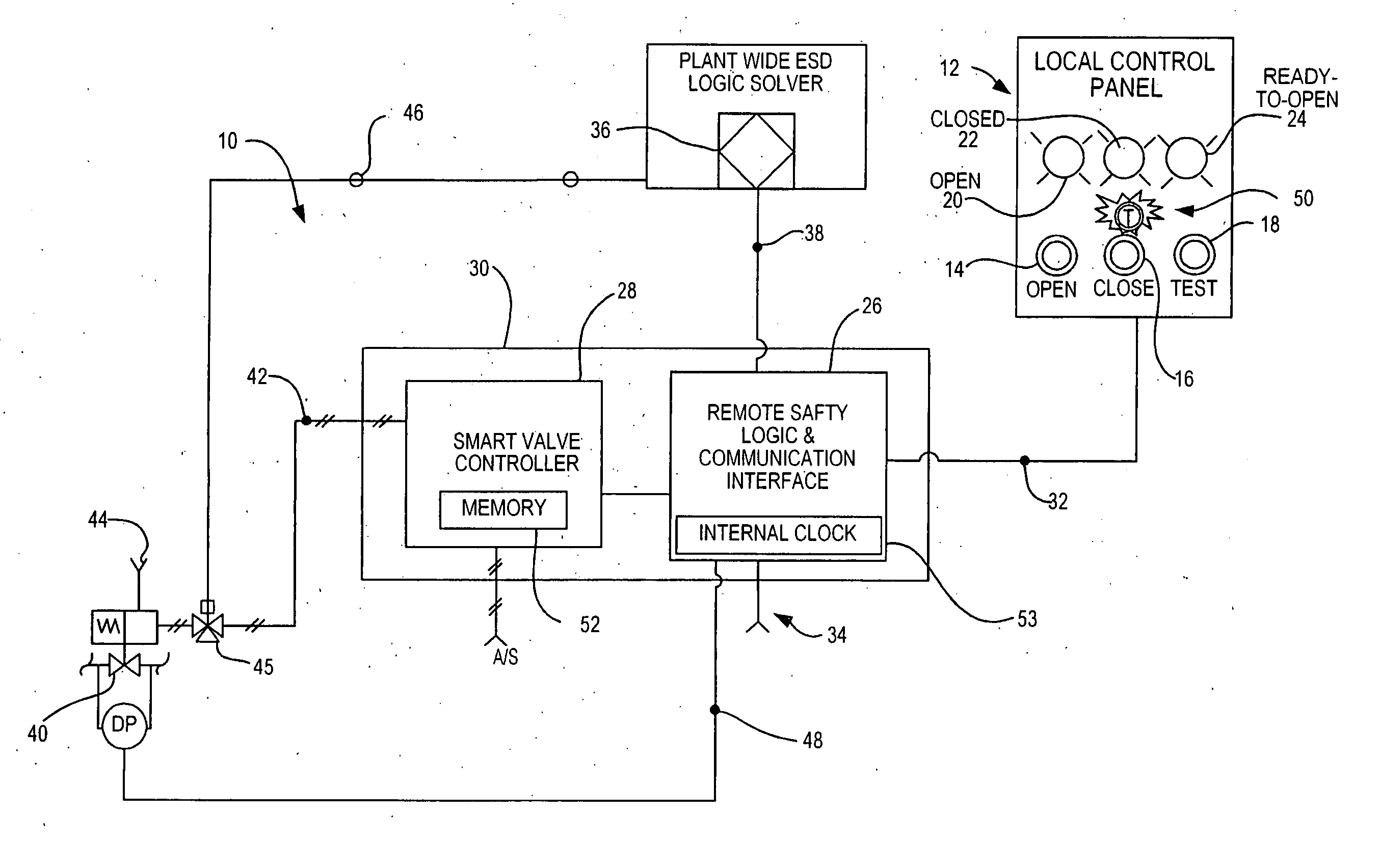
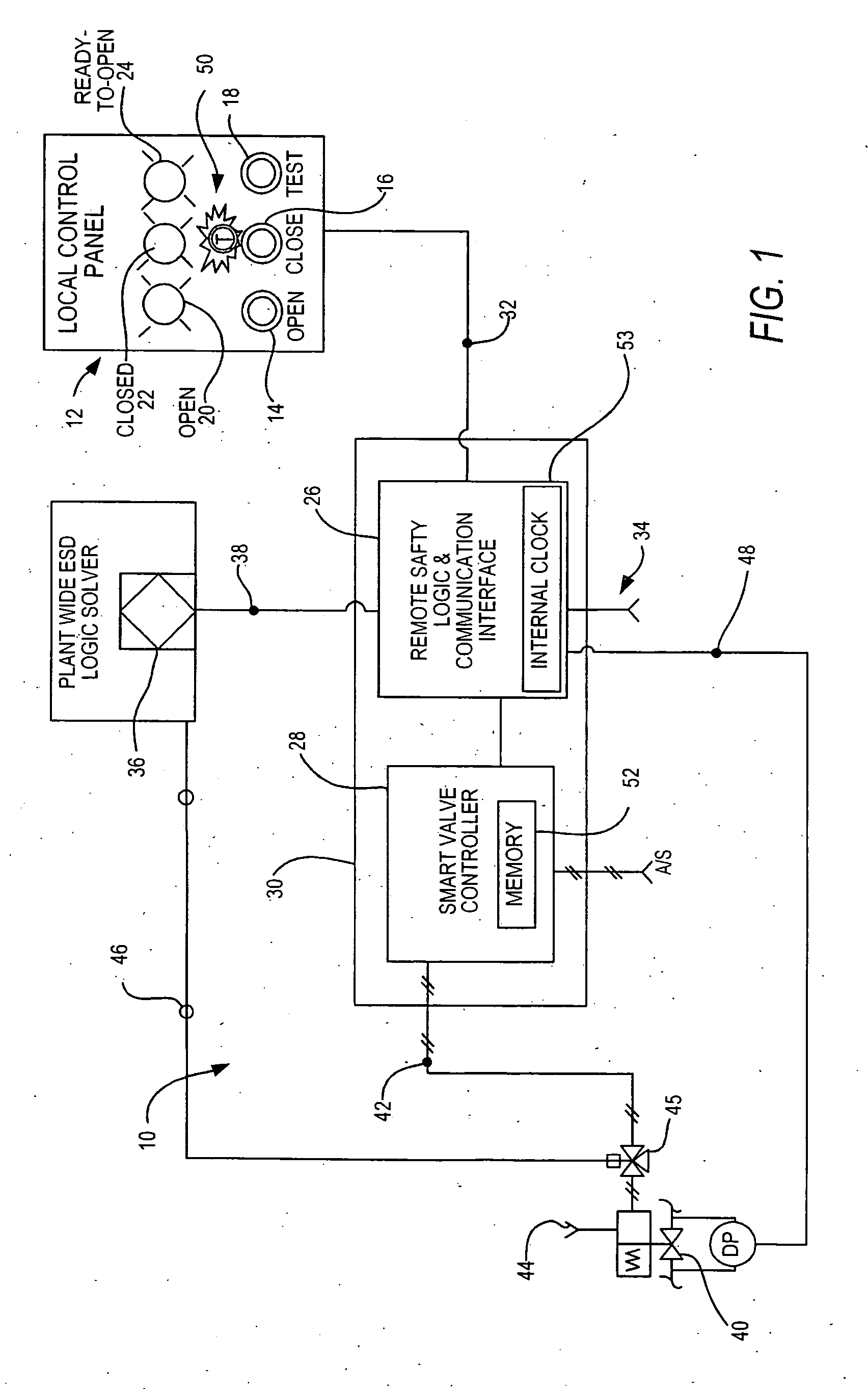
[0043] As illustrated in FIGS. 1-4, the present invention is directed to a system and method for managing plant process risk which include enhanced function indicators, and logic and local interface capabilities in a valve controller, associated with an EIV installed to perform a specific safety instrumented functions (SIF) with an emergency isolation valve (EUV) located in the smart valve controller itself. The advantages of the invention include the reduction of the footprint or size of the plant-wide ESD system through reduced I / O and improved diagnostic coverage of each EIV as final elements is increased through improved testing features and enhanced communications.

[0044] The smart valve controller can be implemented in a known manner, for example, to provide the apparatus described in U.S. Pat. No. 6,186,167 and U.S. application Ser. No. 10 / 116,940, filed Apr. 5, 2002, the disclosures of each of which is incorporated herein by reference in its entirety.

[0045] Implementation o...


PUM


Abstract

A local logic solver operates with a local smart valve controller to control and test a local field-mounted emergency isolation valve device to which provide a local indication of trouble on the device, which is mounted in the field away from the facility's central control panel for the process. Accordingly, the operation of the overall system is simplified by eliminating the need for an external computer to diagnose any problems. A local control panel includes an indicator light substantially adjacent to or in close proximity to the device being monitored to alert personnel of detected faults. Detected faults are time-stamped locally to provide documentation and tracking of elapsed time, starting when the degraded state of the device was detected and first signaled as a problem.

Description

1. FIELD OF THE INVENTION [0001] This invention relates to valve controllers, and in particular to a smart valve controller with integrated fault indicators for emergency isolation valves (EIV). 2. BACKGROUND OF THE INVENTION [0002] As used herein, the term smart valve means a computer-controlled valve with a locally disposed microprocessor or chip programmed for adaptively responding to changing conditions. Known smart valve systems and remote safety logic solvers can be configured to be connected to a central monitoring computer system; however, such a configuration for use in a chemical or petroleum processing facility incurs significant overhead costs due to the requirement for communication links among the distributed mechanisms, such as safety devices. Those overhead costs are compounded since these smart valve systems and remote safety logic solvers are separate entities, but both are used for EIV control. [0003] Prior art smart valve systems include an integrated assembly of...

Claims


Application Information

Patent Timeline
Patent Type & Authority Applications(United States)
IPC IPC(8): G08B21/00
CPCG05B23/0264F16K37/0083F16K37/0091G05B23/0267Y10T137/7761Y10T137/8158Y10T137/8175Y10T137/86397G08B21/187
Inventor FLANDERS, PATRICK S.
Owner SAUDI ARABIAN OIL CO
Why Eureka
Try Eureka