Isolation valve with extended seal life

a technology of isolation valve and seal life, which is applied in the direction of valve details, valve arrangement, slide valve, etc., can solve the problems of increasing operating costs, reducing throughput, and corroding gases contacting the seal

Inactive Publication Date: 2000-05-02
APPLIED MATERIALS INC
View PDF13 Cites 44 Cited by
  • Summary
  • Abstract
  • Description
  • Claims
  • Application Information

AI Technical Summary

Benefits of technology

A purge gas channel 39 is formed in the valve body 11 to deliver a purge gas into the interstitial space between the valve door 12 and the secondary seating surface 16. The purge gas provides additional protection to the o-ring 18 by diluting process gases which penetrate the o-ring seal 18 and migrate into the interior environment of the valve assembly 10.

Problems solved by technology

As a result, the volatile and corrosive gases contact the seals.
The seals currently used are susceptible to attack from these gases and continual exposure requires frequent replacement of the seals, resulting in increased operating costs and decreased throughput.

Method used


Image

  • Isolation valve with extended seal life
  • Isolation valve with extended seal life
  • Isolation valve with extended seal life

Examples


Embodiment Construction

The invention generally provides a new isolation valve assembly which prevents contact between the o-ring seals and the process gases when the valve is in the opened position to provide extended seal life. In one embodiment, a valve assembly is provided which seals a valve door adjacent a primary seating surface during a closed position and which seals the valve door adjacent a secondary seating surface during an opened position. In another embodiment, a purge gas channel is disposed through a valve body between a primary seal and a secondary barrier seal to deliver a purge gas adjacent to the o-ring seals to further prevent contact between the process gases and the primary seal. The invention will be described in detail below with reference to several embodiments.

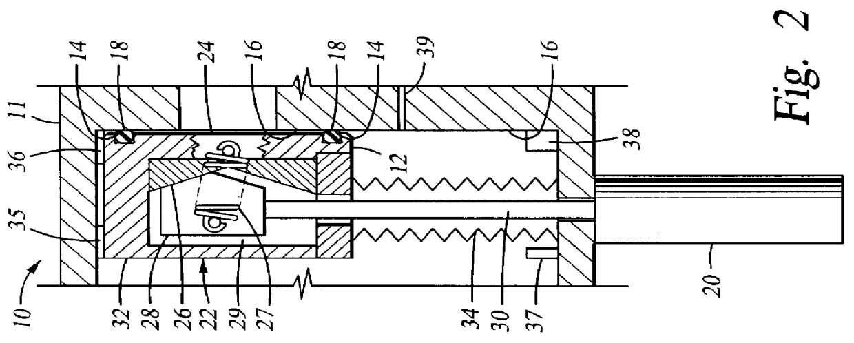
FIG. 2 is a partial cross sectional view of a first embodiment of a valve assembly 10 comprising a valve body 11 having a valve door 12 disposed therein, a primary seating surface 14, and secondary seating surface 16. The ...


PUM


Abstract

A gate valve assembly having a primary and secondary seating surface for preventing process fluids from contacting the seals of the valve is provided. Additionally, a purge gas inlet can be disposed in the valve body to prevent process gases from contacting the seals during operation. Still further, a primary and secondary barrier seal may be provided to prevent process gases from contacting the primary seal. Additionally, a purge gas inlet can be disposed between the primary and secondary seals to further prevent process gases from contacting the primary seal.

Description

1. Field of the InventionThe present invention relates to a valve assembly for sealing an opening in a processing system. More particularly, the invention relates to a valve assembly which prevents exposure of the seals incorporated in the valve assembly to the process environment.2. Background of the Related ArtIn the fabrication of integrated circuits and flat panel displays, various processing chambers and systems are employed to perform multiple deposition and etch processes on substrates to form electronic devices. Examples of some processes include chemical vapor deposition, physical vapor deposition and various etch processes performed in processing systems using volatile and corrosive gases. The corrosive gases typically attack the exposed chamber components including o-ring seals found in valves disposed in exhaust lines connecting vacuum pumps to the processing systems.FIG. 1 is a schematic cross sectional view of a processing chamber 100 showing a chamber body 110 housing...

Claims


Application Information

Patent Timeline
Patent Type & Authority Patents(United States)
IPC IPC(8): F16K3/18F16K3/02
CPCF16K3/184
Inventor SCHNEIDER, GERHARD
Owner APPLIED MATERIALS INC
Why Eureka
Try Eureka