
Method and system for a mass flow controller with reduced pressure sensitivity

a mass flow controller and sensitivity technology, applied in process and machine control, instruments, specific gravity measurement, etc., can solve problems such as tool alarms or unscheduled downtime, damage, etc., to reduce the number of components, reduce the sensitivity to pressure transients, and minimize false flow conditions

Inactive Publication Date: 2007-05-08
BROOKS INSTRUMENT +1
View PDF97 Cites 45 Cited by
  • Summary
  • Abstract
  • Description
  • Claims
  • Application Information

AI Technical Summary

Benefits of technology

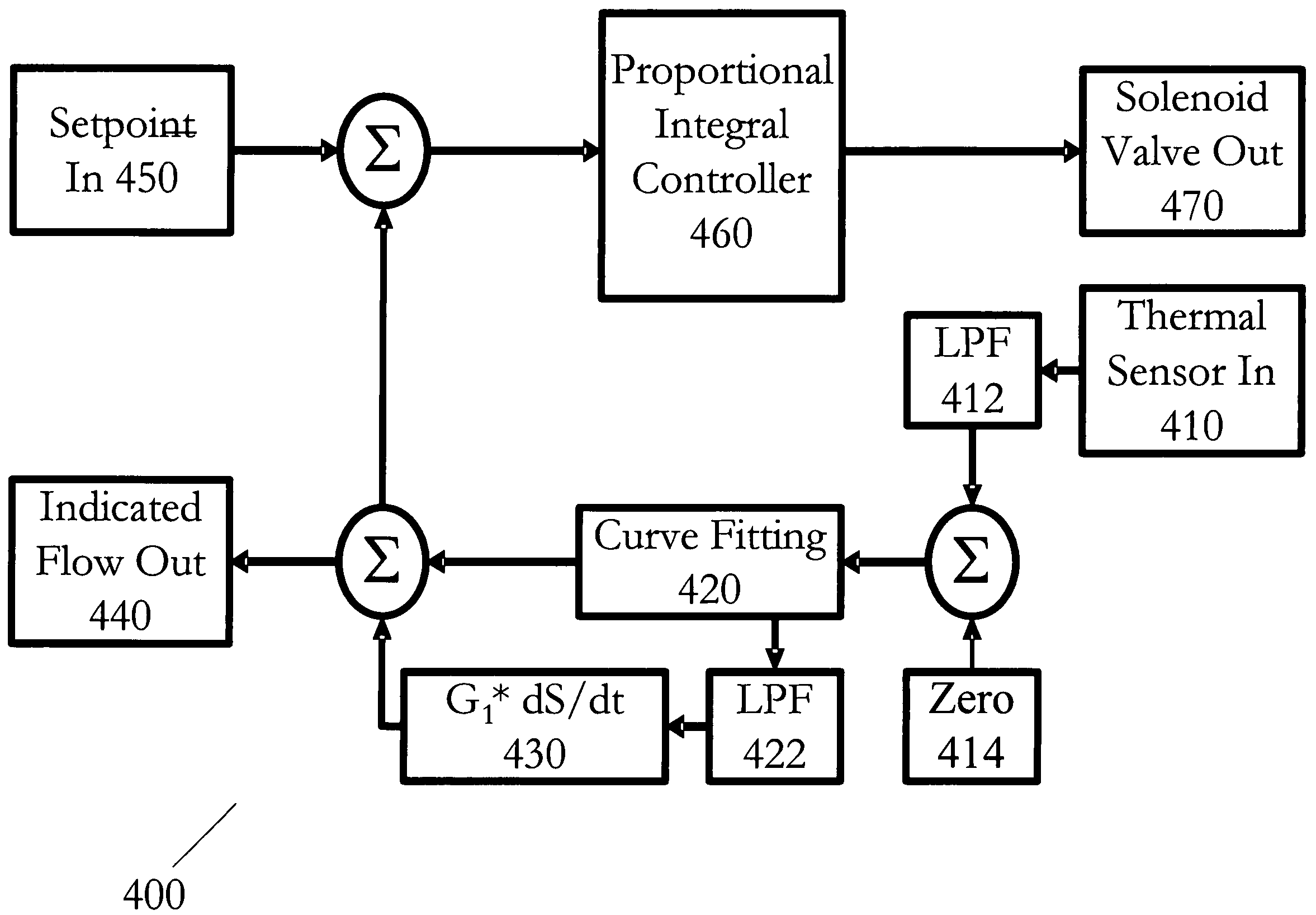
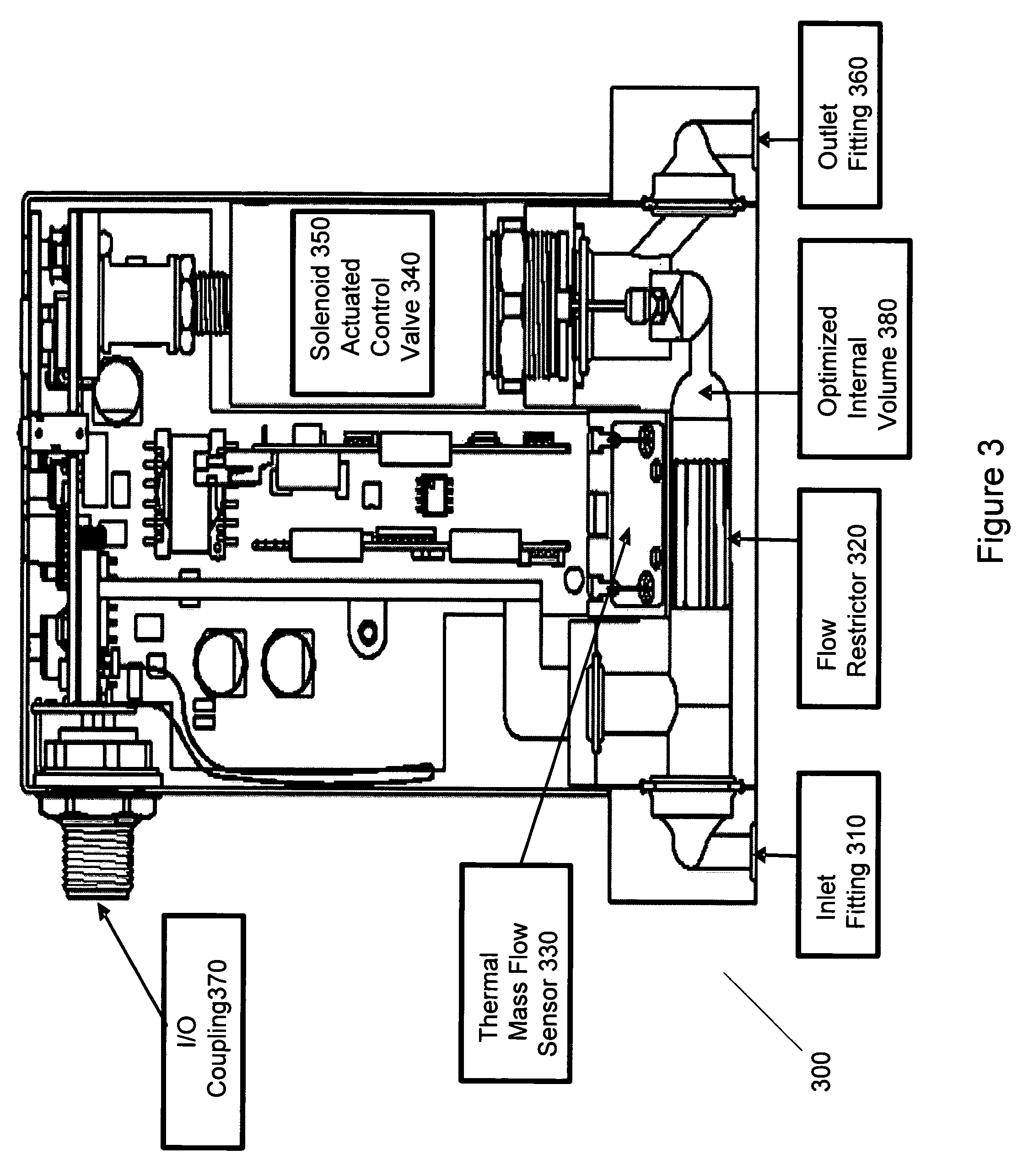
[0012]Systems and methods for mass flow controllers which minimize false flow conditions and display a reduced sensitivity to pressure transients are disclosed. These mass flow controllers may be utilized to stabilize the flow of process gases through a gas stick during upstream pressure disturbances as well as provide an indicated flow signal that more accurately reflects the movement of process gas flowing from the outlet fitting of a mass flow controller. Mass flow controllers of this type may also be utilized to reduce the number of components on a typical gas stick. Reduced sensitivity to pressure transients may be achieved by minimizing the pressure gradients that exists within the volume of the mass flow controller fluid path in order to limit the potential energy contained in compressed or pressurized process gas. Additionally, sensitivity of a mass flow controller to pressure transients may be accomplished by monitoring process gas pressure using a pressure sensor. This pressure signal is utilized in conjunction with a control algorithm to reduce the sensitivity of the mass flow controller during pressure disturbances by canceling the detrimental effect of certain flow components. These mass flow controllers may be used as drop in replacements for legacy mass flow controllers and reduce the cost of gas sticks due to elimination of discrete components such as pressure regulators, gas filters, pressure transducers, local pressure displays, isolation valves, seals, etc.
[0021]In similar embodiments, the control valve is positioned vertically and the optimization minimizes the volume.

Problems solved by technology

However, MFCs of this type, and their control algorithms, may be particularly sensitive to pressure fluctuation in the process gases and may indicate false flow conditions.
Unfortunately, typical techniques for enhancing the bandwidth of the thermal sensor employed by MFCs inject high frequency components into the indicated flow signal that do not reflect the true value of the actual mass flow exiting the outlet fitting of the mass flow controller during upstream pressure disturbances.
This temporary perturbation in indicated flow and actual process gas flow can result in poor transient or steady state stability that can cause wafer damage, tool alarms or unscheduled downtime.

Method used


Image

  • Method and system for a mass flow controller with reduced pressure sensitivity
  • Method and system for a mass flow controller with reduced pressure sensitivity
  • Method and system for a mass flow controller with reduced pressure sensitivity

Examples


Embodiment Construction

[0040]The invention and the various features and advantageous details thereof are explained more fully with reference to the nonlimiting embodiments that are illustrated in the accompanying drawings and detailed in the following description. Descriptions of well known starting materials, processing techniques, components and equipment are omitted so as not to unnecessarily obscure the invention in detail. It should be understood, however, that the detailed description and the specific examples, while indicating preferred embodiments of the invention, are given by way of illustration only and not by way of limitation. After reading the specification, various substitutions, modifications, additions and rearrangements which do not depart from the scope of the appended claims will become apparent to those skilled in the art from this disclosure.

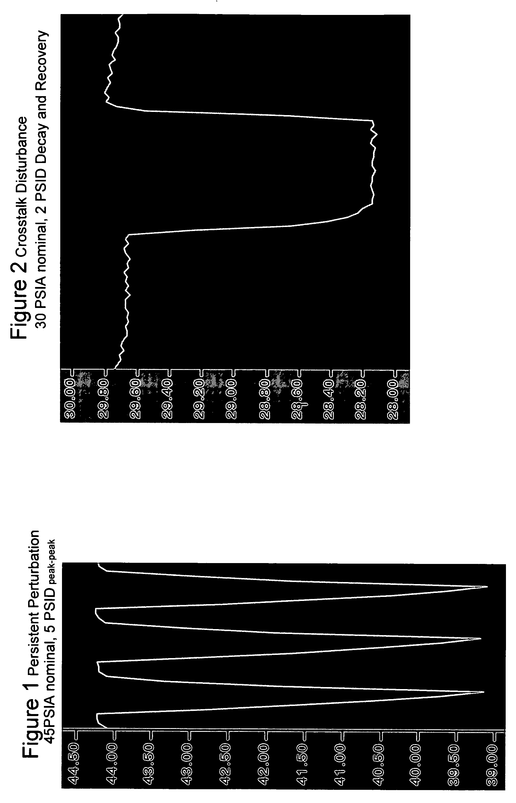
[0041]Before describing embodiments of the present invention, two types of pressure disturbance test which may be utilized to measure the effica...


PUM

PropertyMeasurementUnit
time constantaaaaaaaaaa
pressureaaaaaaaaaa
volumeaaaaaaaaaa

Abstract

Systems and methods for mass flow controllers which minimize false flow conditions and display a reduced sensitivity to pressure transients are disclosed. Pressure gradients that exist within the volume of a mass flow controller fluid path are minimized in order to limit the potential energy contained in compressed or pressurized process gas. Additionally, process gas pressure may be monitored using a pressure sensor. This pressure signal is utilized in conjunction with a control algorithm to cancel the detrimental effect of certain flow components. These mass flow controllers may be used as drop in replacements for legacy mass flow controllers and reduce the cost of gas sticks due to elimination of discrete components such as pressure regulators, gas filters, pressure transducers, local pressure displays, isolation valves, seals, etc.

Description

RELATED APPLICATIONS AND PATENTS[0001]This application is related to U.S. Pat. No. 6,343,617, entitled “System and Method of Operation of a Digital Mass Flow Controller,” by Tinsley et al., issued on Feb. 5, 2002; U.S. Pat. No. 6,640,822, entitled “System and Method of Operation of a Digital Mass Flow Controller,” by Tinsley et al., issued on Nov. 4, 2003; U.S. Pat. No. 6,681,787, entitled “System and Method of Operation of a Digital Mass Flow Controller,” by Tinsley et al., issued on Jan. 27, 2004; U.S. Pat. No. 6,389,364, entitled “System and Method for a Digital Mass Flow Controller,” by Vyers, issued on May 14, 2002; U.S. Pat. No. 6,714,878, entitled “System and Method for a Digital Mass Flow Controller,” by Vyers, issued on Mar. 30, 2004; U.S. Pat. No. 6,445,980, entitled “System and Method for a Variable Gain Proportional-Integral (PI) Controller,” by Vyers, issued on Sep. 3, 2002; U.S. Pat. No. 6,449,571, entitled “System and Method for Sensor Response Linearization,” by Tari...

Claims


Application Information

Patent Timeline
Patent Type & Authority Patents(United States)
IPC IPC(8): G05D11/00G01F1/00G01N7/00G05D7/00G05D7/06
CPCG05D7/0635
Inventor TINSLEY, KENNETH E.TARIQ, FAISAL
Owner BROOKS INSTRUMENT
Learn More