Creating an underbalance condition in a wellbore

a wellbore and underbalance technology, applied in the direction of wellbore/well accessories, sealing/packing, weapons, etc., can solve the problems of underbalanced perforation, affecting the productivity of production wells or the injectivity of injector wells, and a tunnel full of rock debris

Inactive Publication Date: 2005-04-05
SCHLUMBERGER TECH CORP
View PDF15 Cites 44 Cited by
  • Summary
  • Abstract
  • Description
  • Claims
  • Application Information

AI Technical Summary

Problems solved by technology

The process may also generate a tunnel full of rock debris mixed in with the perforator charge debris.
The shock damaged region and loose debris in the perforation tunnels may impair the productivity of production wells or the injectivity of injector wells.
One popular method of obtaining clean perforations is underbalanced perforating.
However, underbalance perforating may not always be effective and may be expensive and unsafe to implement in certain downhole conditions.
However, fracturing is a relatively expensive operation.
Acidizing, another widely used method for removing perforation damage, is not effective for treating sand and loose debris left inside the perforation tunnel.

Method used


Image

  • Creating an underbalance condition in a wellbore
  • Creating an underbalance condition in a wellbore
  • Creating an underbalance condition in a wellbore

Examples


Embodiment Construction

In the following description, numerous details are set forth to provide an understanding of the present invention. However, it will be understood by those skilled in the art that the present invention may be practiced without these details and that numerous variations or modifications from the described embodiments may be possible.

As used here, the terms “up” and “down”; “upper” and “lower”; “upwardly” and “downwardly”; “upstream” and “downstream”; “above” and “below” and other like terms indicating relative positions above or below a given point or element are used in this description to more clearly described some embodiments of the invention. However, when applied to equipment and methods for use in wells that are deviated or horizontal, such terms may refer to a left to right, right to left, or other relationship as appropriate.

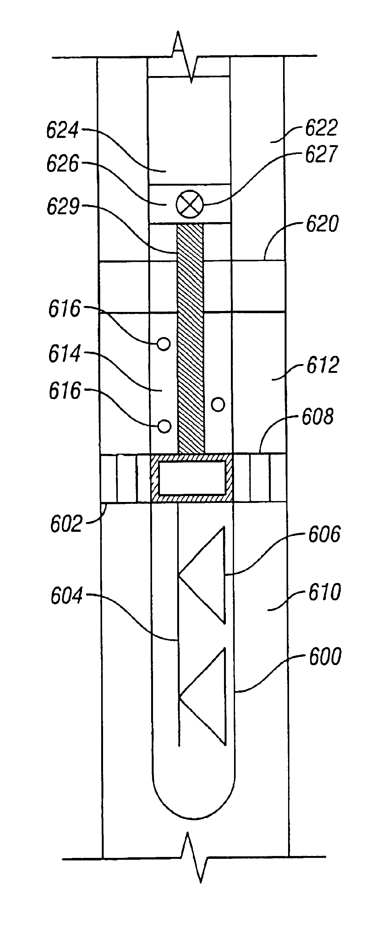
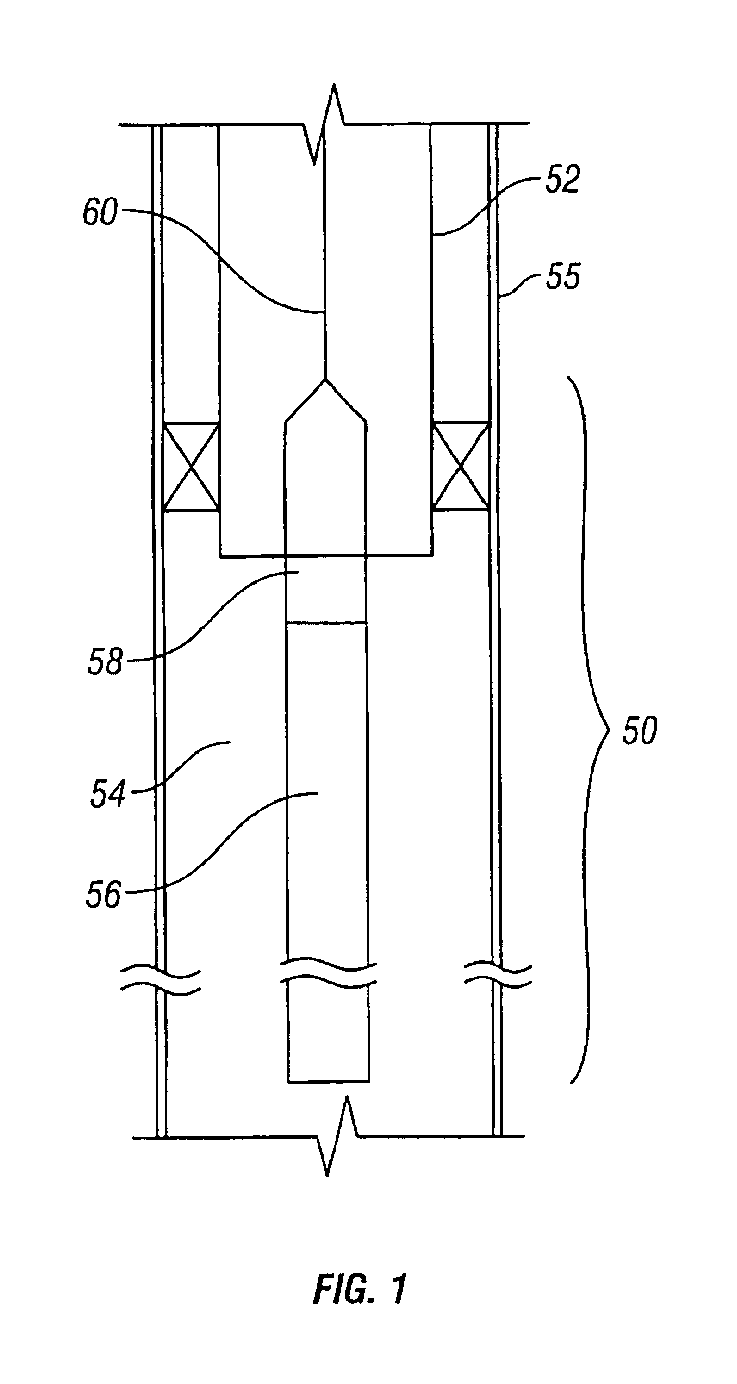
Generally, mechanisms are provided for controlling a local, transient pressure condition in a wellbore. In some cases, it is desirable to lower the local...


PUM


Abstract

An apparatus and method of perforating and surging a section of the wellbore includes running a perforating gun into the well on a string having an isolation valve above the perforating gun, closing the valve, and perforating the well with the isolation valve closed so that the formation is isolated from the well surface. An underbalance pressure is provided above the isolation valve, and then, the isolation valve is opened to surge the formation.

Description

TECHNICAL FIELDThe invention relates generally to improving reservoir communication within a wellbore.BACKGROUNDTo complete a well, one or more formation zones adjacent a wellbore are perforated to allow fluid from the formation zones to flow into the well for production to the surface or to allow injection fluids to be applied into the formation zones. A perforating gun string may be lowered into the well and the guns fired to create openings in casing and to extend perforations into the surrounding formation.The explosive nature of the formation of perforation tunnels shatters sand grains of the formation. A layer of “shock damaged region” having a permeability lower than that of the virgin formation matrix may be formed around each perforation tunnel. The process may also generate a tunnel full of rock debris mixed in with the perforator charge debris. The extent of the damage, and the amount of loose debris in the tunnel, may be dictated by a variety of factors including formati...

Claims


Application Information

Patent Timeline
Patent Type & Authority Patents(United States)
IPC IPC(8): E21B49/08E21B43/117E21B37/08E21B21/00E21B49/00E21B43/02E21B37/00E21B43/04E21B43/11E21B43/119E21B43/25E21B43/26F42D5/00F42D5/045F42B3/00F42B3/02E21B34/00
CPCE21B21/00E21B37/08E21B43/04E21B43/11E21B43/117F42D5/045E21B43/26E21B49/08F42B3/02E21B43/1195E21B2021/006E21B2034/002E21B21/085E21B2200/04
Inventor JOHNSON, ASHLEY B.BEHRMANN, LAWRENCE A.YANG, WENBODOORNBOSCH, FOKKO HARM CORNELIS
Owner SCHLUMBERGER TECH CORP
Why Eureka
Try Eureka