Brake System for Motor Vehicles

a technology for brake systems and motor vehicles, applied in brake systems, vehicle components, transportation and packaging, etc., can solve the problems of not just a minimum braking force, but practically no braking force is actually availabl

Active Publication Date: 2014-01-30
CONTINENTAL TEVES AG & CO OHG
View PDF36 Cites 47 Cited by
  • Summary
  • Abstract
  • Description
  • Claims
  • Application Information

AI Technical Summary

Problems solved by technology

It is disadvantageous that, in an operating mode without actuation of the electrically controllable pressure source, not just a

Method used


Image

  • Brake System for Motor Vehicles
  • Brake System for Motor Vehicles
  • Brake System for Motor Vehicles

Examples


Embodiment Construction

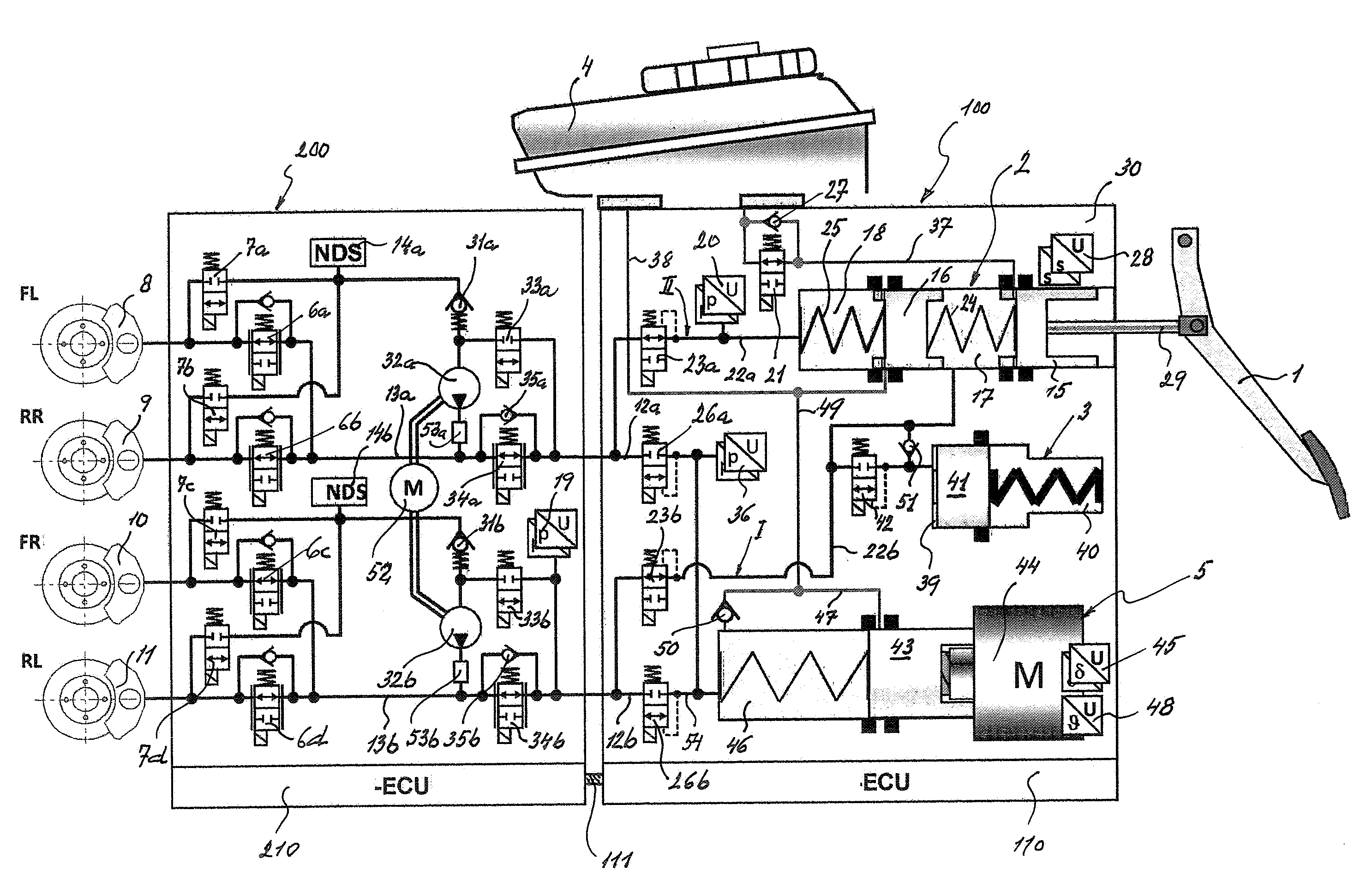
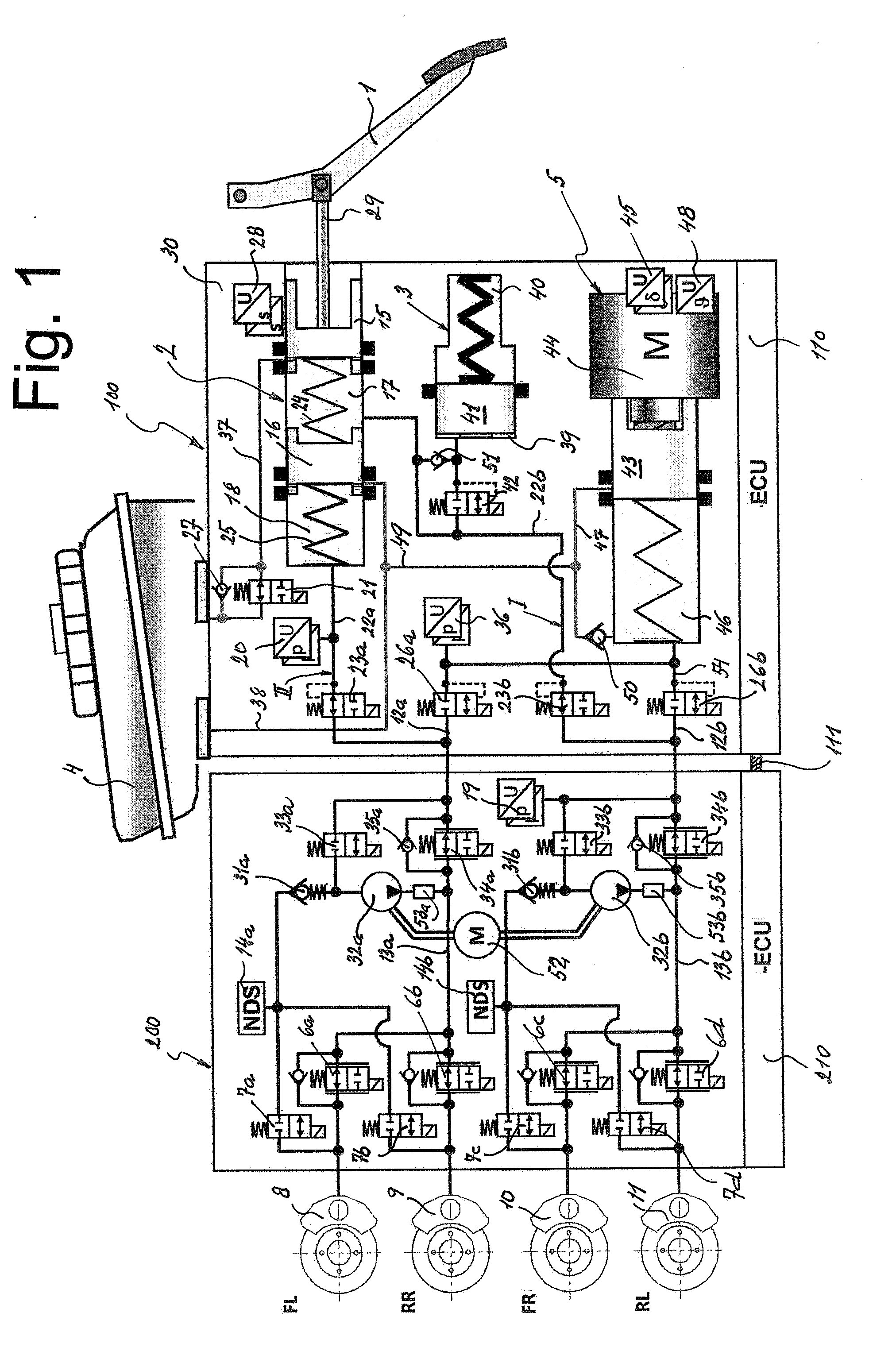
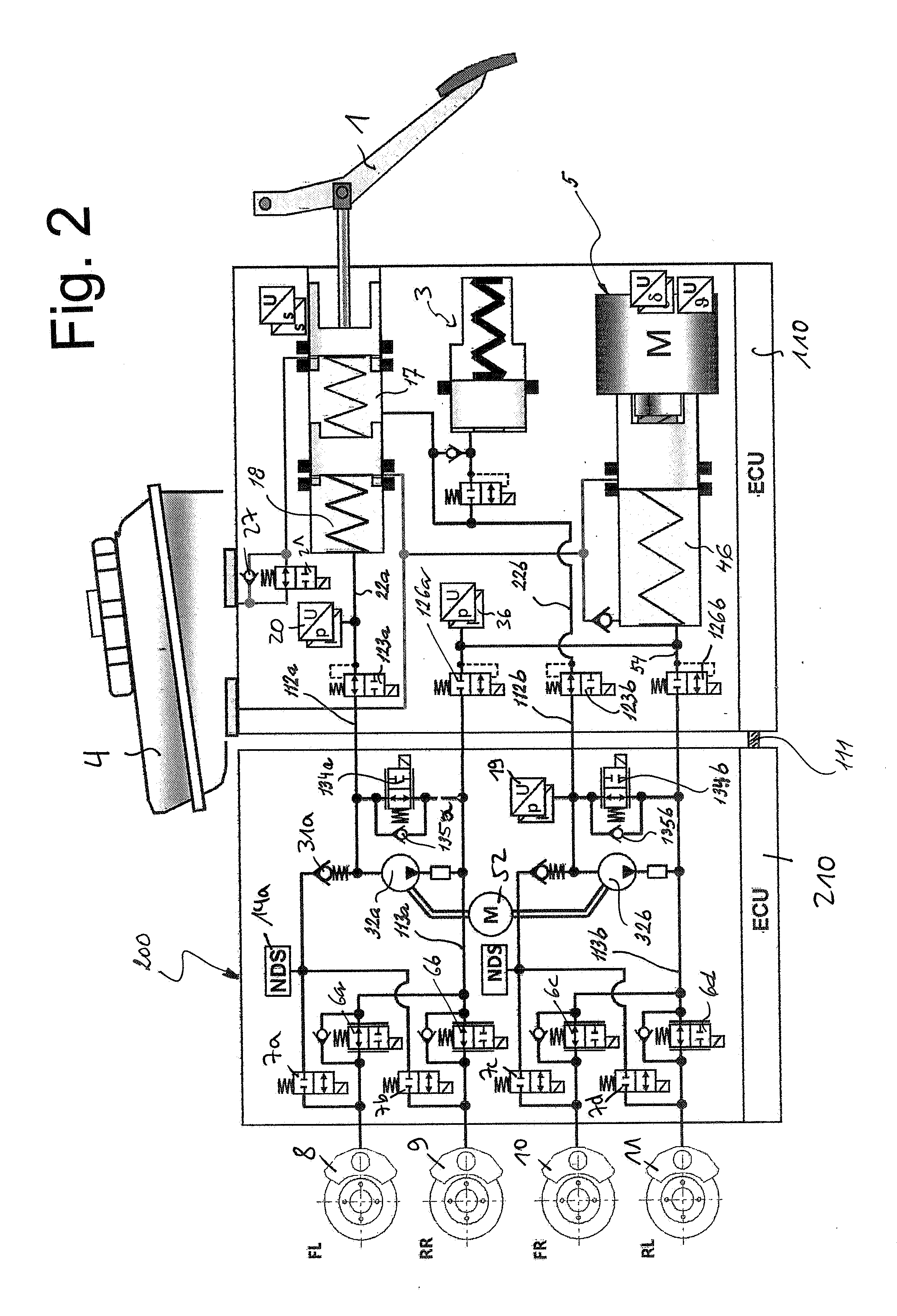
[0022]The brake system represented in the drawing consists essentially of a hydraulic tandem master cylinder 2 which can be actuated by means of an actuating or brake pedal 1, a travel simulator 3 which cooperates with the tandem master cylinder 2, a pressure medium reservoir 4 associated with the tandem master cylinder 2, an electrically controllable pressure source 5, and electrically controllable pressure modulation inlet and outlet valves 6a-6d, 7a-7d which are connected together hydraulically in pairs via center connections to which wheel brakes 8, 9, 10, 11 of a motor vehicle (not shown) are connected. The inlet connections of the inlet valves 6a-6d are supplied in pairs with two pressures, referred to as modulator admission pressures, by means of modulator admission pressure lines 13a, 13b, while the outlet connections of the outlet valves 7a-7d are connected in pairs to a respective low-pressure hydraulic accumulator 14a, 14b in each case. A preferably redundantly implemente...


PUM


Abstract

A motor vehicle brake system operable in a brake-by-wire and fallback modes. The system includes a brake pedal (1), a master cylinder (2), a reservoir (4), a travel simulator (3), an electrically controllable pressure source (5), isolation valves (23a, 23b) pumps (32a, 32b) and a low-pressure accumulator (14a, 14b), an inlet valve (6a-6d) and an outlet valve (7a-7d) for each wheel brake (8, 9, 10, 11), valves (34a, 34b; 134a, 134b) connected to the pumps (32a, 32b), and a control and regulation unit (110, 210). A valve arrangement (23a, 23b) establishes for each brake circuit (I, II) a connection from the pressure chamber (17, 18) of the master cylinder (2) to the modulator admission pressure line (13a, 13b; 113a, 113b) and disconnects the connection when unenergized, the valve arrangement (23a, 23b) preventing the pressure source (5) from being subjected to pressure from the pressure chambers (17, 18).

Description

CROSS REFERENCE TO RELATED APPLICATIONS[0001]This application claims priority to German Patent Application Nos. 102011 007 656.6, filed Apr. 19, 2011, 10 2011 007 655.7, filed Apr. 19, 2011, 10 2012 205 860.5, filed Apr. 11, 2012, and PCT / EP2012 / 056868, filed Apr. 16, 2012.FIELD OF THE INVENTION[0002]The present invention relates to a brake system for motor vehicles which in a brake-by-wire operating mode can be activated both by the vehicle driver and independently of the vehicle driver, and is operated preferably in the brake-by-wire operating mode and can be operated in at least one fallback operating mode in which only operation by the vehicle driver is possible.BACKGROUND AND INTRODUCTORY DESCRIPTION[0003]A brake system in accordance with this invention includes:[0004]a) a brake pedal for actuating a brake master cylinder having a housing and two pistons which are arranged one behind the other and delimit pressure chambers arranged in the housing, to which pressure chambers two...

Claims


Application Information

Patent Timeline
IPC IPC(8): B60T13/58B60T13/68
CPCB60T13/686B60T13/58B60T8/4081
Inventor BILLER, HARALDSTAUDER, PETERBEISIER, MARCOFEIGEL, HANS-JORG
Owner CONTINENTAL TEVES AG & CO OHG
Why Eureka
Try Eureka