Cutting element for a drill bit used in drilling subterranean formations

a drilling bit and drill bit technology, applied in drill bits, drilling accessories, earth-moving mining and mining, etc., can solve the problems of cutter failure due to temperature concerns, cutter design continues to face obstacles, cutter delamination and fracture can occur,

Active Publication Date: 2011-02-10
BAKER HUGHES INC
View PDF101 Cites 109 Cited by
  • Summary
  • Abstract
  • Description
  • Claims
  • Application Information

AI Technical Summary

Problems solved by technology

However, PDC cutter designs continue to face obstacles.
Moreover, in extreme conditions, delamination and fracture of the cutters can occur given the extreme loading and temperatures generated during a drilling operation.
Furthermore, failure of the cutters due to temperature ...

Method used


Image

  • Cutting element for a drill bit used in drilling subterranean formations
  • Cutting element for a drill bit used in drilling subterranean formations
  • Cutting element for a drill bit used in drilling subterranean formations

Examples


Embodiment Construction

[0013]The present disclosure may be better understood, and its numerous features and advantages made apparent to those skilled in the art by referencing the accompanying drawings.

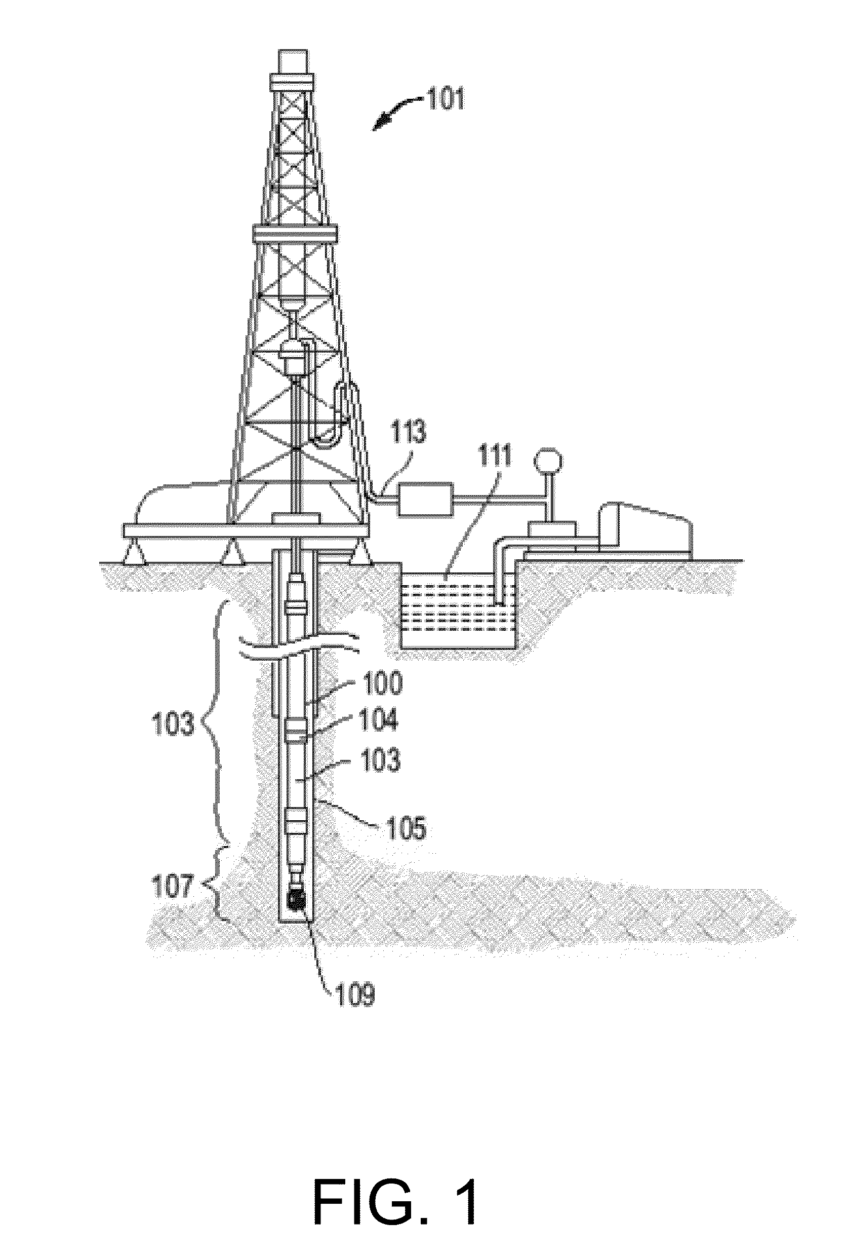
[0014]FIG. 1 includes an illustration of a subterranean drilling operation.

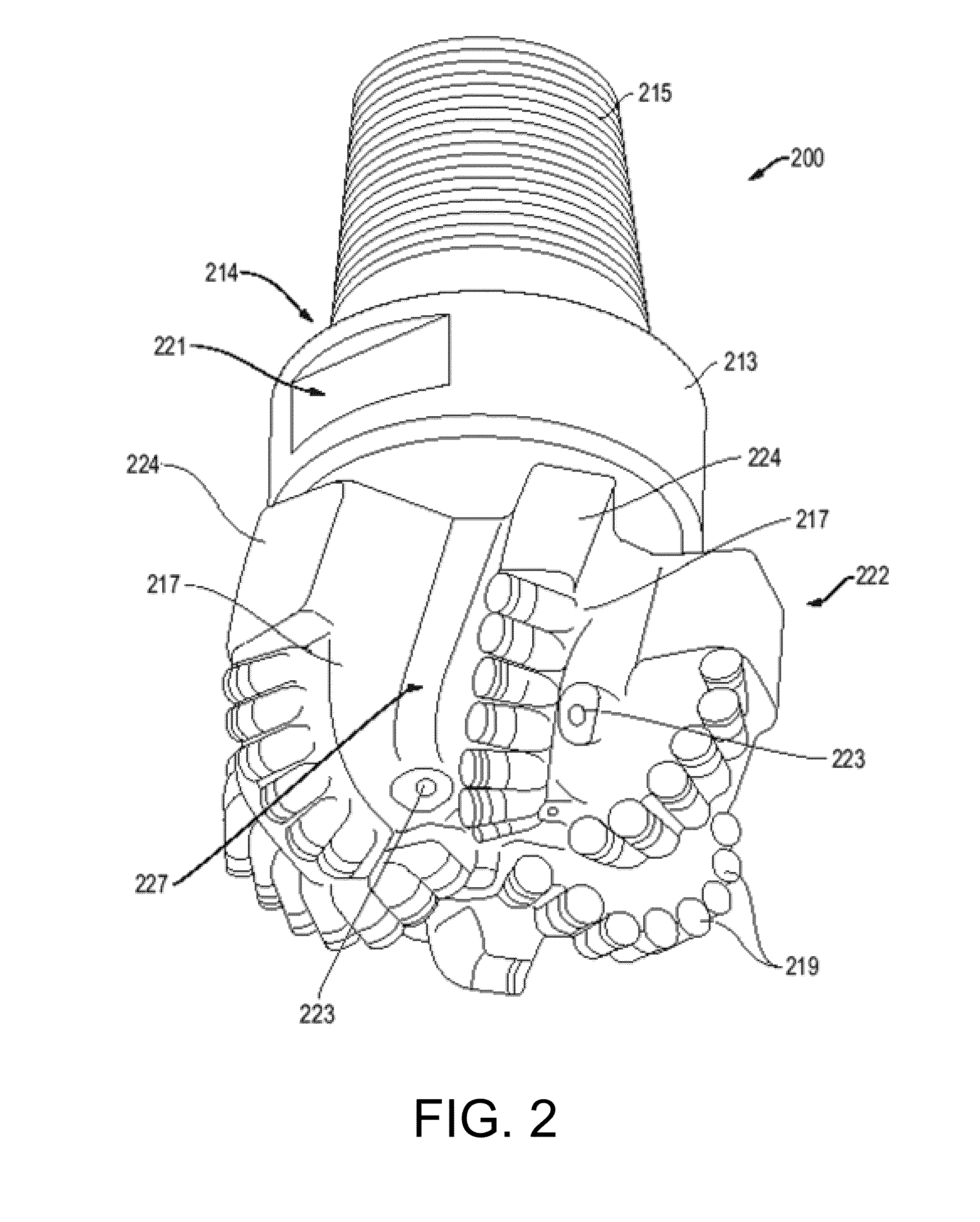
[0015]FIG. 2 includes an illustration of a drill bit in accordance with an embodiment.

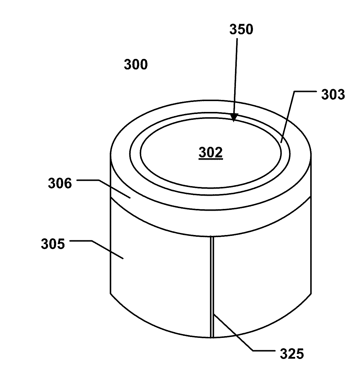
[0016]FIGS. 3A-3C include cross-sectional illustrations and a perspective view of cutter elements in accordance with embodiments.

[0017]FIGS. 4A-4D include cross-sectional illustrations of cutter elements in accordance with embodiments.

[0018]FIGS. 5A-5D include cross-sectional illustrations of cutter elements in accordance with embodiments.

[0019]FIG. 6 includes a cross-sectional illustration of a cutter element in accordance with an embodiment.

[0020]FIG. 7 includes a top view illustration of a cutter element in accordance with an embodiment.

[0021]FIGS. 8A-8C include cross-sectional illustrations and a perspective view of cutter elements in accordance...


PUM

PropertyMeasurementUnit
Angleaaaaaaaaaa
Hardnessaaaaaaaaaa

Abstract

A cutting element for use in a drill bit for drilling subterranean formations includes a cutting body having a substrate including a rear surface, an upper surface, and a peripheral side surface extending between the rear surface and the upper surface, and a superabrasive layer overlying the upper surface of the substrate. The cutting element further includes a sleeve surrounding the peripheral side surface of the cutting body and comprising a superabrasive layer bonded to an external surface of the sleeve.

Description

CROSS-REFERENCE TO RELATED APPLICATION(S)[0001]The present application claims priority from U.S. Provisional Patent Application No. 61 / 223,748, filed Jul. 8, 2009, entitled “Cutting Element for a Drill Bit Used in Drilling Subterranean Formations,” naming inventors Chaitanya K. Vempati, Suresh G. Patel, Jack T. Oldham, Danielle M. Fuselier, Jim Powers and Nicholas J. Lyons, which application is incorporated by reference herein in its entirety.BACKGROUND[0002]1. Field of the Disclosure[0003]The following disclosure is directed to cutting elements for use in drill bits, and particularly cutting elements incorporating a cutting body and a sleeve.[0004]2. Description of the Related Art[0005]In the past, rotary drill bits have incorporated cutting elements employing superabrasive materials. Within the industry there has been widespread use of synthetic diamond cutters using polycrystalline diamond compacts, otherwise termed “PDC” cutters. Such PDC cutters may be self supported, otherwise...

Claims


Application Information

Patent Timeline
IPC IPC(8): E21B10/52
CPCC22C26/00E21B10/573E21B10/567C22C2204/00B24D18/0009E21B10/5676
Inventor VEMPATI, CHAITANYA K.PATEL, SURESH G.OLDHAM, JACK THOMASFUSELIER, DANIELLE M.POWERS, JIMLYONS, NICHOLAS J.
Owner BAKER HUGHES INC
Why Eureka
Try Eureka