Chemical dispensing systems and positive displacement flow meters therefor
- Summary
- Abstract
- Description
- Claims
- Application Information
AI Technical Summary
Benefits of technology
Problems solved by technology
Method used
Image
Examples
Embodiment Construction
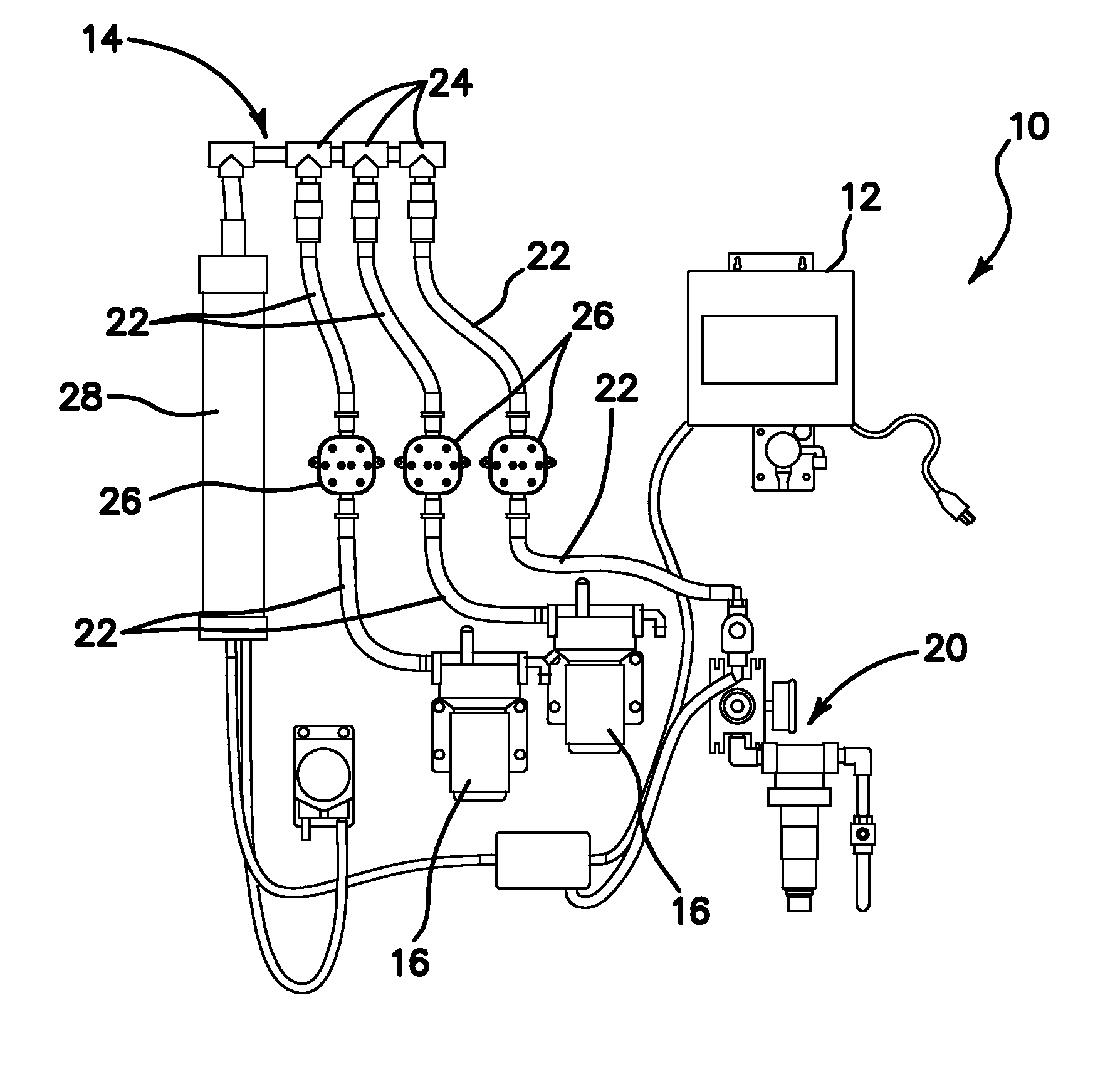
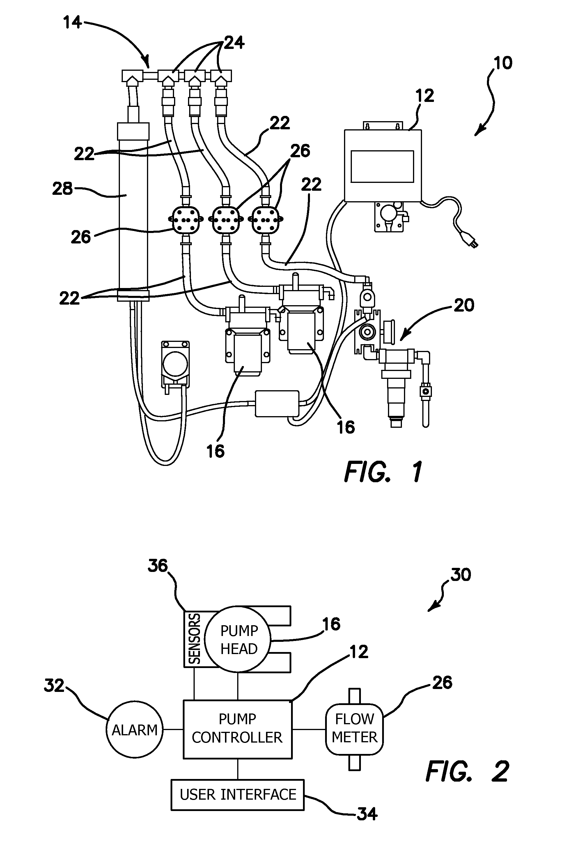
[0050]Referring now more particularly to the drawings, there is shown in FIG. 1 a schematic view of a fluid dispensing system 10. The system 10, as illustrated, comprises a control unit 12, a mixing channel 14, a first pump 16, a second pump 16, and a water inlet assembly 20. Fluid lines 22 extend between each of the pumps 16, and the water inlet assembly 20 and fittings 24 on the mixing chamber 14. Flow meters 26, constructed in accordance with the principles of the present invention, are disposed in each of the fluid lines 22, as shown. A mixing reservoir 28 is also fluidly connected to the mixing chamber 14, for purposes to be described below.
[0051]FIG. 2 illustrates a control system 30 which may be used in connection with a dispensing system like the system 10 shown in FIG. 1. The control system 30 comprises the pump controller 12, a pump head 16, and a flow meter 26. Additional components which are connected to the control unit 12 comprise an alarm 32, which may be audible, vis...
PUM
 Abstract
Description
Claims
Application Information
 - R&D
- Intellectual Property
- Life Sciences
- Materials
- Tech Scout
- Unparalleled Data Quality
- Higher Quality Content
- 60% Fewer Hallucinations
Browse by: Latest US Patents, China's latest patents, Technical Efficacy Thesaurus, Application Domain, Technology Topic, Popular Technical Reports.
© 2025 PatSnap. All rights reserved.Legal|Privacy policy|Modern Slavery Act Transparency Statement|Sitemap|About US| Contact US: help@patsnap.com


